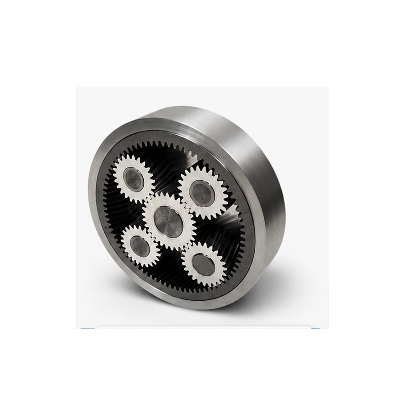
Description
Planet gears for load-sharing epicyclic stages, supplied as matched quantities with bore, bearing or bushing interfaces defined by the carrier design.
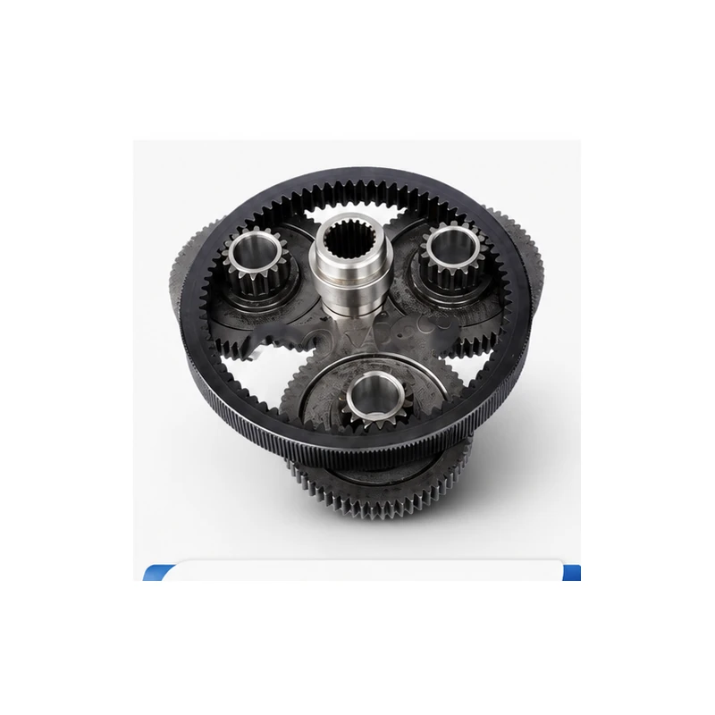
Construction and engineering scope
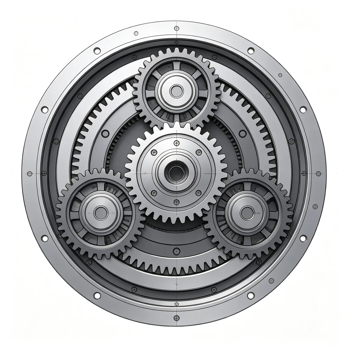
Planet gears both spin about their own axes and orbit with the carrier. Consistency between the planet gears is important for balanced load distribution.
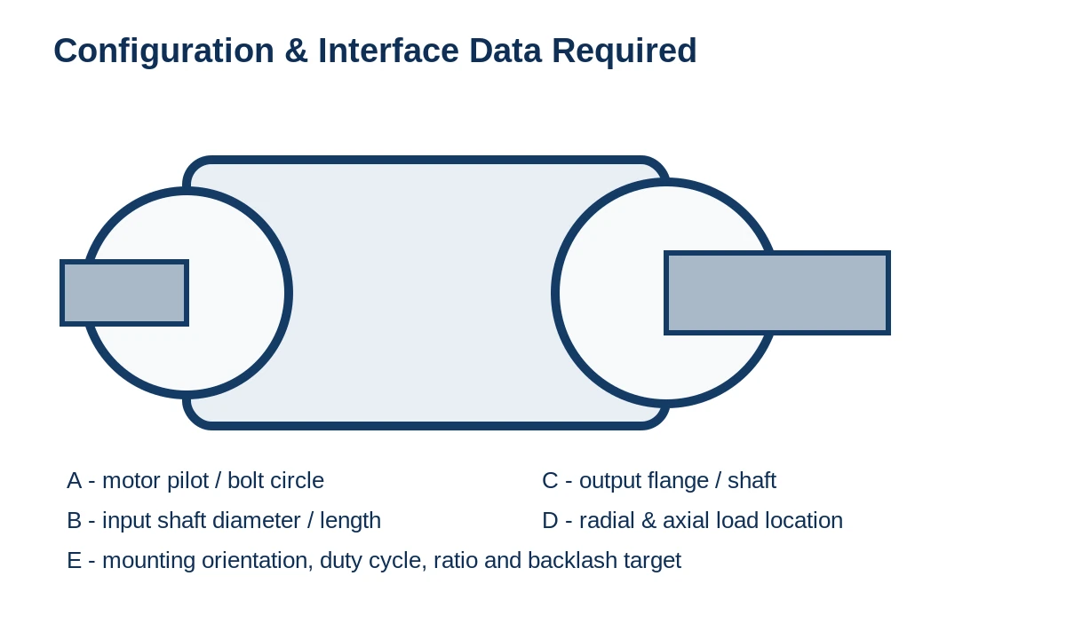
Additional engineering views
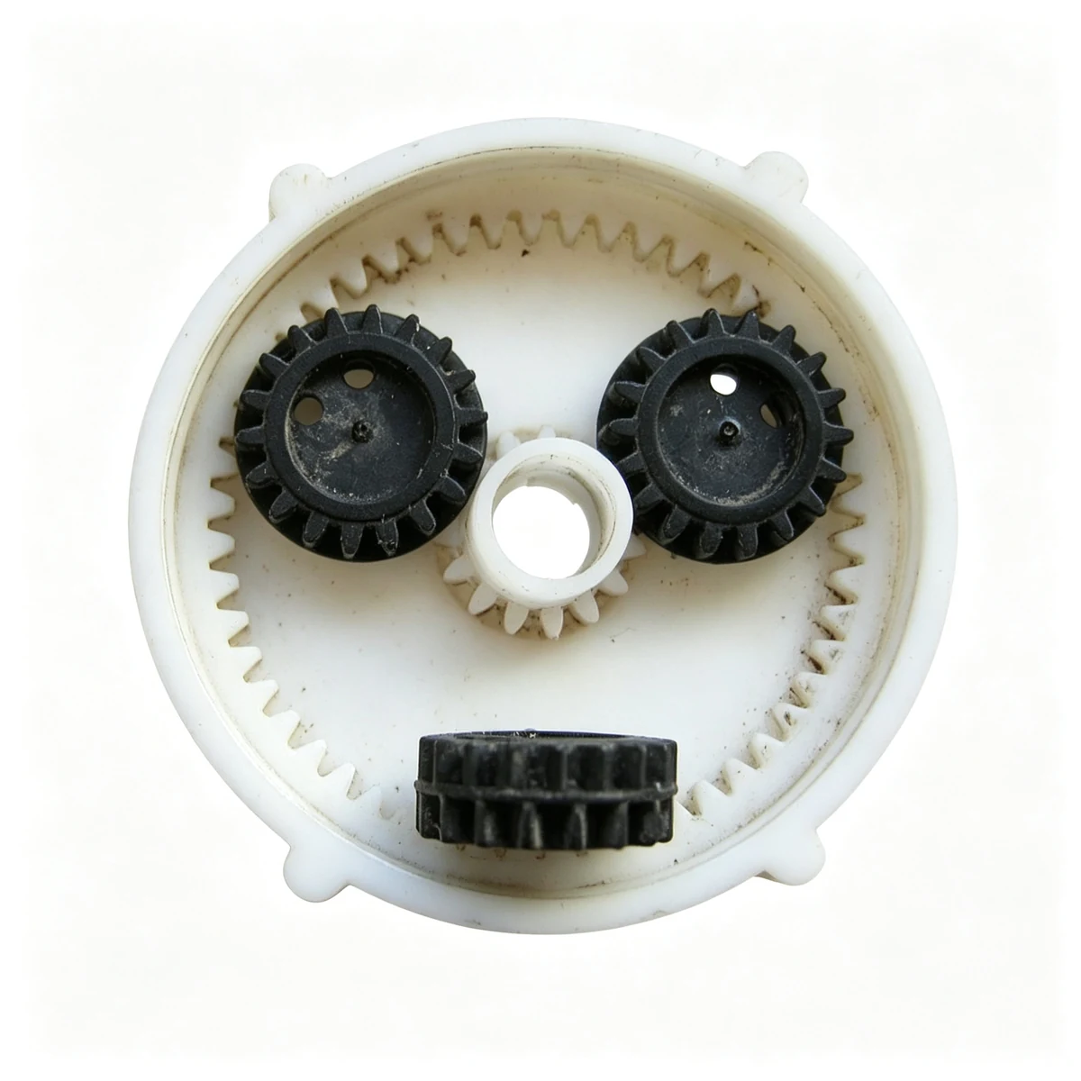
Technical parameters
| Quantity per stage | typically multiple planets; exact count by design |
|---|---|
| Tooth data | module/DP, tooth count, pressure angle, helix if applicable |
| Bore / bearing seat | by carrier and pin design |
| Material / heat treatment | selected to tooth stress and life target |
| Matched-set control | recommended for multi-planet load sharing |
| Inspection | runout, tooth geometry, hardness, dimensions |
Typical configurable options are shown for RFQ planning only. Final values are fixed by the approved drawing, material specification, heat treatment, ratio, duty and inspection plan.
Applications and selection
Confirm planet quantity, pin/bearing design, mating sun and ring tooth data, face width, duty and target life. For wear replacements, inspect the full set rather than replacing one damaged planet in isolation.
Customization options
Engineering review can cover tooth count and ratio, spur or helical geometry, material and heat treatment, motor or shaft interface, output flange or spline, bearing arrangement, lubrication, sealing, backlash class and inspection documentation. Features are confirmed against the approved drawing rather than assumed from a similar model.
Installation and maintenance
Check shaft alignment, pilot fit, fastener grade and tightening method before commissioning. Do not exceed the confirmed continuous or peak torque, radial load, axial load or input speed. For replacement work, verify the mounting drawing and output interface before ordering.
Quality and inspection
Inspection planning can include material traceability, hardness, tooth geometry, runout, dimensional inspection and assembly checks according to the RFQ and approved quality plan. Ask for the required inspection level before quotation.
FAQ
Can you manufacture from a drawing or sample?
Yes, the engineering review can start from a drawing, sample, tooth data or a complete gearbox identification. Final feasibility is confirmed after dimensional and material review.
What information is needed for a replacement?
Send model or nameplate, quantity, ratio, motor or input speed, output torque or duty, shaft/flange dimensions, mounting drawing and clear photos. For individual gears, add tooth count, module or DP, pressure angle, face width and material/heat-treatment requirements if known.