Description
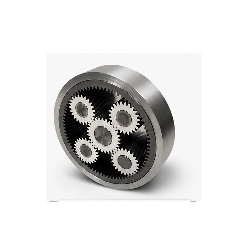
Planet carrier and pin assembly engineering for planetary gear stages where stiffness, pin location, bearing support and output interface must be controlled together.
Construction and engineering scope
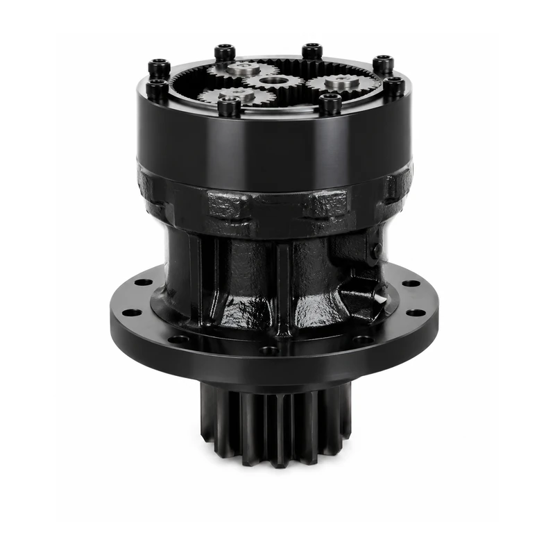
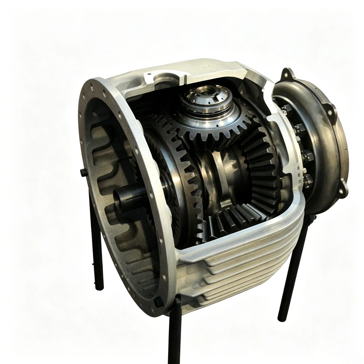
The carrier locates the planet pins and often acts as the output member. Its rigidity and geometric accuracy influence load sharing between planets and output runout.
Additional engineering views
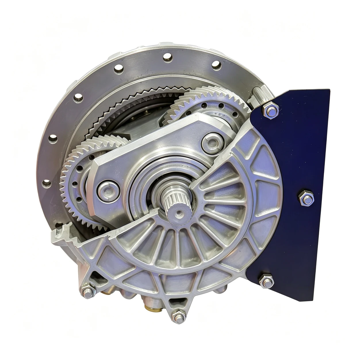
Technical parameters
| Carrier style | single plate, double plate, cage or integrated output |
|---|---|
| Planet pin layout | number and pitch circle by gear geometry |
| Output interface | shaft, spline, flange or custom |
| Bearing / bushing seats | by duty and speed |
| Material | alloy steel or engineered casting/forging by design |
| Inspection | pin position, runout, bore/shaft dimensions |
Typical configurable options are shown for RFQ planning only. Final values are fixed by the approved drawing, material specification, heat treatment, ratio, duty and inspection plan.
Applications and selection
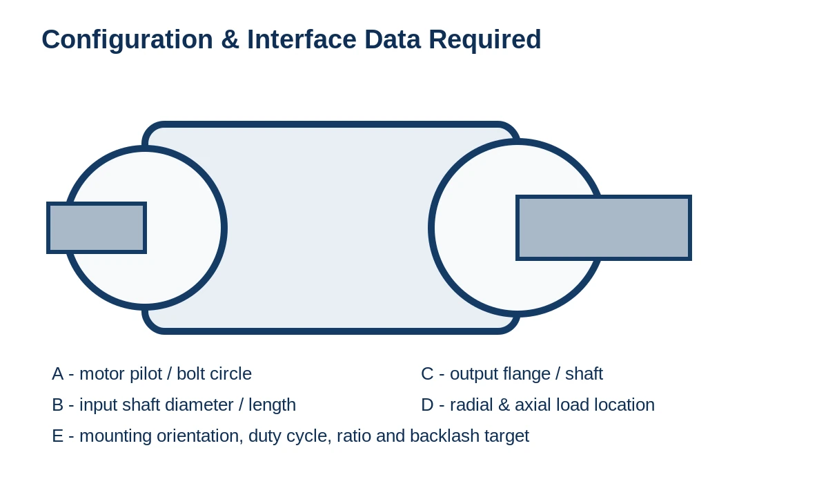
Provide the complete planetary stage drawing or the sun/ring/planet tooth counts and center geometry. Output torque, radial/axial load and bearing arrangement are needed to size the carrier safely.
Customization options
Engineering review can cover tooth count and ratio, spur or helical geometry, material and heat treatment, motor or shaft interface, output flange or spline, bearing arrangement, lubrication, sealing, backlash class and inspection documentation. Features are confirmed against the approved drawing rather than assumed from a similar model.
Installation and maintenance
Check shaft alignment, pilot fit, fastener grade and tightening method before commissioning. Do not exceed the confirmed continuous or peak torque, radial load, axial load or input speed. For replacement work, verify the mounting drawing and output interface before ordering.
Quality and inspection
Inspection planning can include material traceability, hardness, tooth geometry, runout, dimensional inspection and assembly checks according to the RFQ and approved quality plan. Ask for the required inspection level before quotation.
FAQ
Can you manufacture from a drawing or sample?
Yes, the engineering review can start from a drawing, sample, tooth data or a complete gearbox identification. Final feasibility is confirmed after dimensional and material review.
What information is needed for a replacement?
Send model or nameplate, quantity, ratio, motor or input speed, output torque or duty, shaft/flange dimensions, mounting drawing and clear photos. For individual gears, add tooth count, module or DP, pressure angle, face width and material/heat-treatment requirements if known.