Description
Planet Carriers And Assemblies
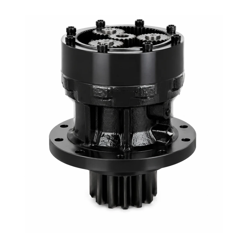
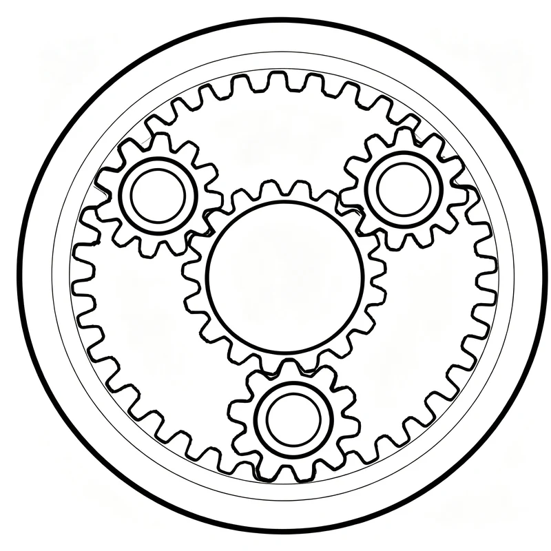
The planet carrier controls planet position, pin support, alignment, and the load path into or out of the gear train. A carrier assembly can include pins, bearings or bushings, thrust elements, splines, and output hubs depending on the gearbox architecture.
Carrier Functions
Carrier stiffness and pin accuracy influence mesh alignment and load sharing. The design must account for torque reaction, planet-bearing loads, deflection, fatigue at pin bores, and the connection to the output shaft or hub.
Assembly Inputs
| Input | Required Detail |
|---|---|
| Planet count | Number and angular spacing |
| Pin geometry | Diameter, fit, retention, hardness |
| Bearing arrangement | Needle, roller, bushing, or drawing-defined support |
| Carrier interface | Spline, shaft, flange, hub, weldment |
| Planet gear data | Bore, width, thrust faces, mass |
| Load data | Continuous/peak torque, cycles, reversals, shock |
Inspection Focus
For replacement carriers, inspect pin-bore wear, cracking, fretting, thrust-face damage, spline wear, and runout. If planet gears show uneven wear around the circumference, carrier distortion or bearing clearance should be investigated before duplicating the old part.
Supply Format
Projects can be reviewed as a machined carrier component or as an assembled subassembly when the drawing defines planets, pins, bearings, and retention hardware. The approved drawing remains the production authority.
FAQ
Can you supply a carrier as a complete assembly?
Yes, when the bill of materials and assembly requirements are defined or can be established from a sample.
Why is pin position accuracy important?
Pin position affects planet spacing and load sharing, which influences noise, stress, and gear life.
Can a worn carrier be measured for replacement?
A sample can support reverse engineering, but wear must be distinguished from the intended original geometry.
What load data helps most?
Continuous torque, peak torque, reversals, duty cycle, output speed, and shock events are especially useful.
Data Note: Carrier descriptions are engineering guidance. No specific carrier dimensions or material claims are published without a controlled drawing or confirmed source.
Review A Carrier Assembly
Share ratio, input speed and power, required output torque, duty cycle, mounting space, shaft or flange interface, environment, quantity, and any drawing or existing gearbox reference. Our engineering team will review the configuration before quotation.