Category Archives: Uncategorized

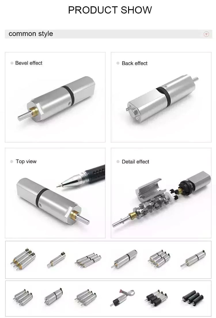
China Brushless Mini Plastic DC Gear Motor TGP01D-A130 For Toy Car

TGP01D-A130 TGP01S-A130 TGP02D-A130 TGP02S-A130

Brushless Mini Plastic DC Gear Motor TGP01D-A130 For Toy Car

Characters of Mini Plastic DC Equipment Motor

  • Voltage: 3v 6v
  • Reduction Ratio: 1/40 8,,1/100 20,1/100 and 80,1/220,1/256,1/288
  • Dize:64.2 X 22.5 X 8een.8mm,64.2mm duration micro motor
  • The double facet
  • can match with wheels, foremost wires, and battery bins
  • Samples can be despatched 1st. The shipping and delivery time is fifteen-20 times

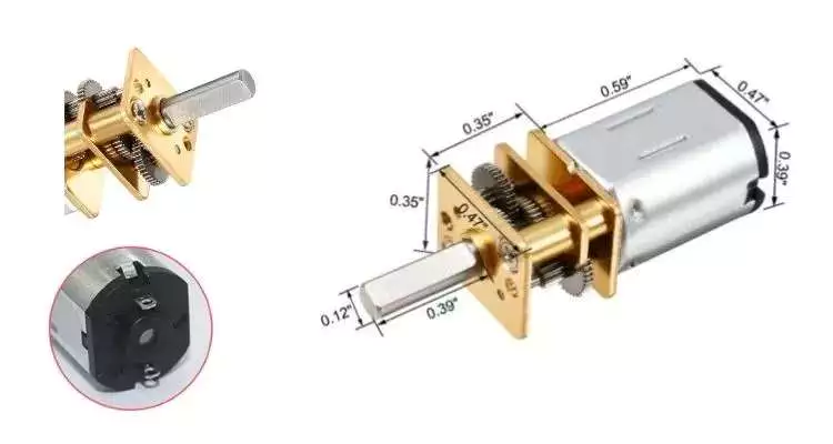
Gear motor dimension (mm)


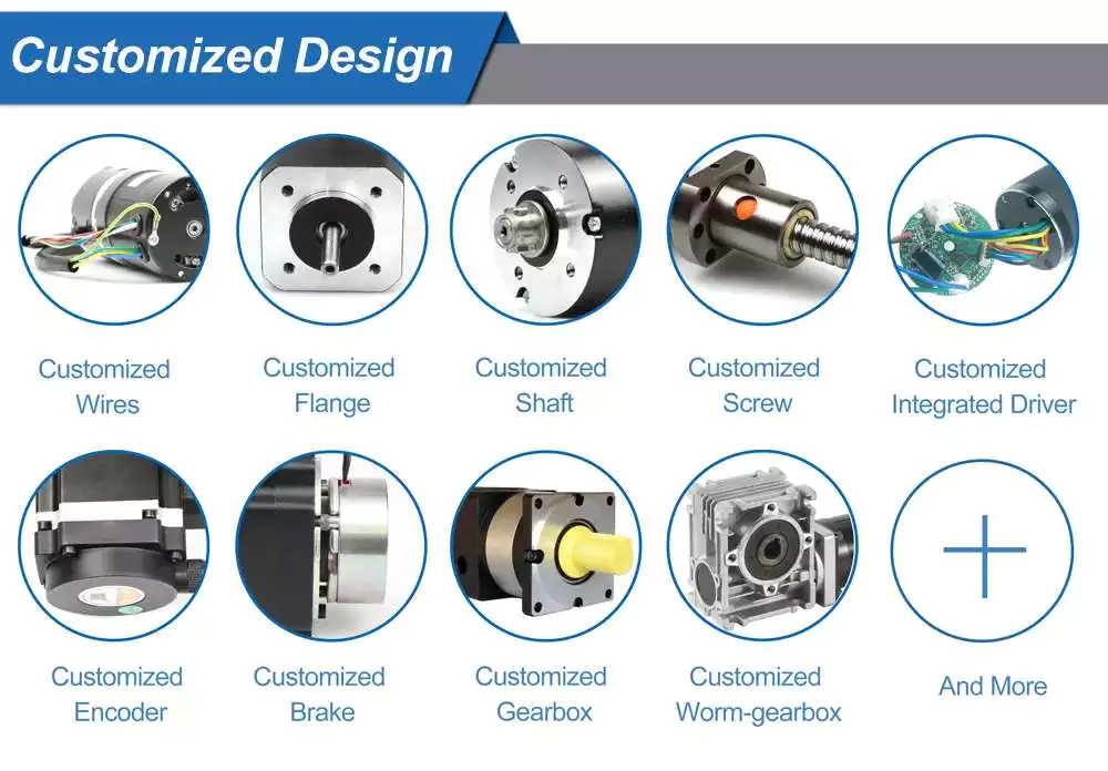
Customization Support of Mini Plastic DC Equipment Motor

See what else tailored solutions we can offer you to you?


1. gear 2. shaft 3. rear shaft 4. encoder 5. water-proof

Observe: All these customization companies is not going to lead to new tooling fees, just can have our equipment motors match your design demands flawlessly
1. Equipment type: Helical, worm, spur,

Substance: powder, copper, machined, plastic. all gears are developed by our engineers
2. Shaft: hole on the shaft, sq. shaft, screw shaft…
3. Rear shaft: for encoder mounting or 1 more part you want to mount
4. Encoder: corridor sensor encoder
5. Water-proof: shield motor nicely
6. an additional customization ask for if you require

Other Plastic Standard dc toy motor

What is a DC motor?

DC motor is a sort of motor that converts electrical vitality into mechanical strength. DC motor obtains energy by means of DC and converts this power into mechanical rotation.
The DC motor utilizes the magnetic area generated by the generated current to provide energy for the movement of the rotor fastened in the output shaft. The output torque and speed count on the electrical input and the style of the motor.

How do DC Motors operate?

The time period ‘DC motor’ is utilized to refer to any rotary electrical device that converts immediate current electrical vitality into mechanical power. DC motors can vary in measurement and power from modest motors in toys and appliances to large mechanisms that energy cars, pull elevators and hoists, and push metal rolling mills. But how do DC Motors perform?

DC motors incorporate 2 essential components: a stator and an armature. The stator is the stationary part of a motor, while the armature rotates. In a DC motor, the stator provides a rotating magnetic subject that drives the armature to rotate.

A basic DC motor uses a stationary established of magnets in the stator, and a coil of wire with a existing operating by means of it to make an electromagnetic field aligned with the middle of the coil. One particular or far more windings of insulated wire are wrapped around the core of the motor to focus the magnetic subject.

The windings of insulated wire are linked to a commutator (a rotary electrical switch), that applies an electrical existing to the windings. The commutator makes it possible for every single armature coil to be energized in change, making a constant rotating force (acknowledged as torque).

When the coils are turned on and off in sequence, a rotating magnetic discipline is created that interacts with the distinct fields of the stationary magnets in the stator to create torque, which causes it to rotate. These important functioning principles of DC motors permit them to convert the electrical power from immediate recent into mechanical strength through the rotating motion, which can then be employed for the propulsion of objects.

Added details

Benefits of a Planetary Motor

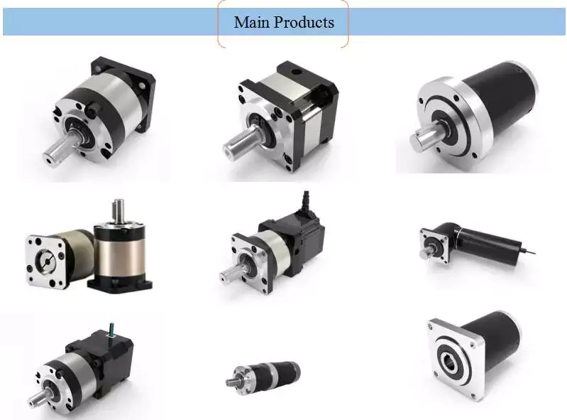
If you’re looking for an affordable way to power a machine, consider purchasing a Planetary Motor. These units are designed to provide a massive range of gear reductions, and are capable of generating much higher torques and torque density than other types of drive systems. This article will explain why you should consider purchasing 1 for your needs. And we’ll also discuss the differences between a planetary and spur gear system, as well as how you can benefit from them.

planetary gears

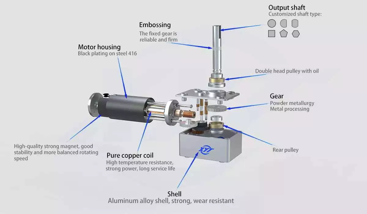
Planetary gears in a motor are used to reduce the speed of rotation of the armature 8. The reduction ratio is determined by the structure of the planetary gear device. The output shaft 5 rotates through the device with the assistance of the ring gear 4. The ring gear 4 engages with the pinion 3 once the shaft is rotated to the engagement position. The transmission of rotational torque from the ring gear to the armature causes the motor to start.
The axial end surface of a planetary gear device has 2 circular grooves 21. The depressed portion is used to retain lubricant. This lubricant prevents foreign particles from entering the planetary gear space. This feature enables the planetary gear device to be compact and lightweight. The cylindrical portion also minimizes the mass inertia. In this way, the planetary gear device can be a good choice for a motor with limited space.
Because of their compact footprint, planetary gears are great for reducing heat. In addition, this design allows them to be cooled. If you need high speeds and sustained performance, you may want to consider using lubricants. The lubricants present a cooling effect and reduce noise and vibration. If you want to maximize the efficiency of your motor, invest in a planetary gear hub drivetrain.
The planetary gear head has an internal sun gear that drives the multiple outer gears. These gears mesh together with the outer ring that is fixed to the motor housing. In industrial applications, planetary gears are used with an increasing number of teeth. This distribution of power ensures higher efficiency and transmittable torque. There are many advantages of using a planetary gear motor. These advantages include:
Motor

planetary gearboxes

A planetary gearbox is a type of drivetrain in which the input and output shafts are connected with a planetary structure. A planetary gearset can have 3 main components: an input gear, a planetary output gear, and a stationary position. Different gears can be used to change the transmission ratios. The planetary structure arrangement gives the planetary gearset high rigidity and minimizes backlash. This high rigidity is crucial for quick start-stop cycles and rotational direction.
Planetary gears need to be lubricated regularly to prevent wear and tear. In addition, transmissions must be serviced regularly, which can include fluid changes. The gears in a planetary gearbox will wear out with time, and any problems should be repaired immediately. However, if the gears are damaged, or if they are faulty, a planetary gearbox manufacturer will repair it for free.
A planetary gearbox is typically a 2-speed design, but professional manufacturers can provide triple and single-speed sets. Planetary gearboxes are also compatible with hydraulic, electromagnetic, and dynamic braking systems. The first step to designing a planetary gearbox is defining your application and the desired outcome. Famous constructors use a consultative modeling approach, starting each project by studying machine torque and operating conditions.
As the planetary gearbox is a compact design, space is limited. Therefore, bearings need to be selected carefully. The compact needle roller bearings are the most common option, but they cannot tolerate large axial forces. Those that can handle high axial forces, such as worm gears, should opt for tapered roller bearings. So, what are the advantages and disadvantages of a helical gearbox?

planetary gear motors

When we think of planetary gear motors, we 10d to think of large and powerful machines, but in fact, there are many smaller, more inexpensive versions of the same machine. These motors are often made of plastic, and can be as small as 6 millimeters in diameter. Unlike their larger counterparts, they have only 1 gear in the transmission, and are made with a small diameter and small number of teeth.
They are similar to the solar system, with the planets rotating around a sun gear. The planet pinions mesh with the ring gear inside the sun gear. All of these gears are connected by a planetary carrier, which is the output shaft of the gearbox. The ring gear and planetary carrier assembly are attached to each other through a series of joints. When power is applied to any of these members, the entire assembly will rotate.
Compared to other configurations, planetary gearmotors are more complicated. Their construction consists of a sun gear centered in the center and several smaller gears that mesh with the central sun gear. These gears are enclosed in a larger internal tooth gear. This design allows them to handle larger loads than conventional gear motors, as the load is distributed among several gears. This type of motor is typically more expensive than other configurations, but can withstand the higher-load requirements of some machines.
Because they are cylindrical in shape, planetary gear motors are incredibly versatile. They can be used in various applications, including automatic transmissions. They are also used in applications where high-precision and speed are necessary. Furthermore, the planetary gear motor is robust and is characterized by low vibrations. The advantages of using a planetary gear motor are vast and include:
Motor

planetary gears vs spur gears

A planetary motor uses multiple teeth to share the load of rotating parts. This gives planetary gears high stiffness and low backlash – often as low as 1 or 2 arc minutes. These characteristics are important for applications that undergo frequent start-stop cycles or rotational direction changes. This article discusses the benefits of planetary gears and how they differ from spur gears. You can watch the animation below for a clearer understanding of how they operate and how they differ from spur gears.
Planetary gears move in a periodic manner, with a relatively small meshing frequency. As the meshing frequency increases, the amplitude of the frequency also increases. The amplitude of this frequency is small at low clearance values, and increases dramatically at higher clearance levels. The amplitude of the frequency is higher when the clearance reaches 0.2-0.6. The amplitude increases rapidly, whereas wear increases slowly after the initial 0.2-0.6-inch-wide clearance.
In high-speed, high-torque applications, a planetary motor is more effective. It has multiple contact points for greater torque and higher speed. If you are not sure which type to choose, you can consult with an expert and design a custom gear. If you are unsure of what type of motor you need, contact Twirl Motor and ask for help choosing the right 1 for your application.
A planetary gear arrangement offers a number of advantages over traditional fixed-axis gear system designs. The compact size allows for lower loss of effectiveness, and the more planets in the gear system enhances the torque density and capacity. Another benefit of a planetary gear system is that it is much stronger and more durable than its spur-gear counterpart. Combined with its many advantages, a planetary gear arrangement offers a superior solution to your shifting needs.
Motor

planetary gearboxes as a compact alternative to pinion-and-gear reducers

While traditional pinion-and-gear reducer design is bulky and complex, planetary gearboxes are compact and flexible. They are suitable for many applications, especially where space and weight are issues, as well as torque and speed reduction. However, understanding their mechanism and working isn’t as simple as it sounds, so here are some of the key benefits of planetary gearing.
Planetary gearboxes work by using 2 planetary gears that rotate around their own axes. The sun gear is used as the input, while the planetary gears are connected via a casing. The ratio of these gears is -Ns/Np, with 24 teeth in the sun gear and -3/2 on the planet gear.
Unlike traditional pinion-and-gear reducer designs, planetary gearboxes are much smaller and less expensive. A planetary gearbox is about 50% smaller and weighs less than a pinion-and-gear reducer. The smaller gear floats on top of 3 large gears, minimizing the effects of vibration and ensuring consistent transmission over time.
Planetary gearboxes are a good alternative to pinion-and-gear drive systems because they are smaller, less complex and offer a higher reduction ratio. Their meshing arrangement is similar to the Milky Way, with the sun gear in the middle and 2 or more outer gears. They are connected by a carrier that sets their spacing and incorporates an output shaft.
Compared to pinion-and-gear reduces, planetary gearboxes offer higher speed reduction and torque capacity. As a result, planetary gearboxes are small and compact and are often preferred for space-constrained applications. But what about the high torque transfer? If you’re looking for a compact alt

China Hangzhou Impact Resistance Small Gear Mc Nylon Plastic Gear

Edited

CX


Plastic Gears For Projects

When creating plastic gears for a undertaking, engineers should take into account a range of running parameters, including torque, rotational pace, and shock hundreds. Other aspects to contemplate consist of the necessary clearance and inertia. If these are out of management, option answers may incorporate escalating the equipment width. The last item need to also be durable sufficient to face up to harsh running circumstances.
The choice of resin is also essential. Some are resistant to oil and grease, but some may possibly impact the functionality of the gear. Furthermore, lubricants should be picked cautiously, as some may chemically assault plastics. This means meticulously deciding on suited resin for the project’s plastic gear is vital.
Plastic gears are typically used in packaging tools, modest conveyors, and agricultural machinery. They are also typically used in planetary gear sets. These gears transmit electricity via appropriate angles on the shaft and are, as a result, a lot more effective than worm gears. Worm gears also make thrust masses but are typically utilized in lower horsepower apps.

Plastic Gears For Tiny Electrical Motors

Plastic gears are utilized to generate tiny electric motors. They are offered in a variety of materials. Normally, they are produced of engineering plastics this sort of as nylon and MC nylon. Plastic gears are also accessible with stainless steel hubs. Sometimes, plastic gears are reinforced with a tiny volume of carbon fiber.
Plastic gears are softer than metallic gears and require less lubrication. Nevertheless, plastic gears can nevertheless deteriorate with oil. These resources should only be lubricated when they should be utilized under reduced friction and reasonably substantial-temperature circumstances. Plastic gears are also considerably less likely to crack than metal gears.
Plastic gears need to not be treated with CZPT oils. Rather, the oil should be non-polar. Polarity is a house of a molecule that has an effect on how it behaves at distinct temperatures. Synthetic hydrocarbon oils are non-polar and do not deteriorate plastics. They are mixed with bulking agents and additives to give them acceptable viscosity and temperature properties.
Plastic gears are cheaper than metal gears, so they are an superb option for tiny robots or other modest equipment. They are typically produced of nylon, which signifies they can be employed with all varieties of wheels.

Q&A

Q1. When can I get the value?

A: We normally quote in 24 hours after acquiring your inquiry. If you are urgent, Remember to contact us or enable us know in your electronic mail so we can prioritize your inquiry.

Q2. How lengthy is the lead time for the mold?

A: It all relies upon on the dimension and complexity of the mildew. Usually, the shipping time is 25-35 times. If the CZPT is straightforward and insignificant, we can do it inside of 15 times.

Q3. I never have drawings how must I start off a new task?

A: You can supply us with samples, and we will help complete the drawing style.

This autumn. How to make sure solution high quality before shipping and delivery?

A: If you do not occur to our manufacturing unit and there is no third-celebration inspection, We will be your inspector. We will give you a video with details of the creation approach, including process stories, product dimensions, structural and floor details, packaging particulars, and many others.

As a plastic equipment rack and plastic equipment supplier, we always goal to offer the greatest good quality merchandise and the most extensive solutions and seem forward to cooperating with you.

Additional data

How to Maximize Gear Motor Reliability

A gearmotor is a mechanical device used to transmit torque from 1 location to another. As its name implies, it is designed to rotate 1 object relative to another. Its main use is to transmit torque from 1 point to another. The most common types of gear motors are: worm, spur, and helical. Each of these has specific functions and can be used for a variety of applications. Reliability is also an important factor to consider when choosing a gearmotor.

Applications of a gear motor

Despite its small size, a gear motor has many applications. These include heavy machinery lifts, hospital beds, and power recliners. It is also found in many everyday products, such as electromechanical clocks and cake mixers. Its versatility allows it to produce a high force from a small electric motor. Here are some of its most common uses. You can also find a gear motor in many household appliances and vehicles.
Before selecting a gearmotor, consider the specifications of the machine you need to power. You should consider its size, weight, and ambient conditions, which include temperature regimes, noise levels, and contaminating sources. You should also take into account the envelope size, mounting method, and orientation. Other considerations include the expected service life, maintenance scope, and control type. The most suitable gearmotor for your specific application will be 1 that can handle the load.
The motor and gearbox types can be mixed and matched, depending on the application. A 3-phase asynchronous motor and a permanent magnet synchronous servomotor are common choices for these devices. The type of motor and gearbox combination you choose will determine the power supply, the efficiency of the motor, and cost. Once you understand the application, it will be easy to integrate a gear motor into your system.
When used in industrial applications, gear motors are effective for reducing the speed of rotating shafts. One third of all industrial electric motor systems use gearing to reduce output speed. They can also save energy, which benefits the workers who operate them. In fact, industrial electric motor systems are responsible for nearly 1-10th of the carbon dioxide emissions that are produced by fossil-fueled power plants. Fortunately, efficiency and reliability are just 2 of the benefits of using gear motors.
Motor

Types

Before choosing a gearmotor, it is important to understand its specifications. The key factors to consider are the size, weight, and noise level of the gearmotor. Additionally, the power, torque, and speed of the motor are important factors. Specifications are also important for its operating environment, such as the temperature and the level of ingress protection. Finally, it is important to determine its duty cycle to ensure it will operate properly. To choose a suitable gearmotor, consult the specifications of your application.
Some common applications of gearmotors include packaging equipment, conveyors, and material handling applications. They also come with several advantages, including their ability to control both position and speed. This makes them ideal for applications where speed and positioning are crucial. Parallel-shaft gear units, for instance, are commonly used in conveyors, material handling, and steel mills. They are also able to operate in high-precision manufacturing. For these reasons, they are the most popular type of gearmotor.
There are 3 common types of gears. Helical gears have teeth that are inclined at 90 degrees to the axis of rotation, making them more efficient. Helicoidal gears, meanwhile, have a lower noise level and are therefore preferred for applications requiring high torque. Worm gears are preferred for applications where torque and speed reduction are important, and worm gears are suited for those conditions. They also have advantages over spur gears and worm gears.
The application of a gear motor is almost limitless. From heavy machine lifts to hospital bed lifting mechanisms, gear motors make it possible to use a small rotor at a high speed. Their lightweight construction also allows them to move heavy loads, such as cranes, but they do so slowly. Gear motors are an excellent choice in applications where space is an issue. A few common applications are discussed below. When choosing a gear motor, remember to choose the best size and application for your needs.
Motor

Functions

A gearmotor’s speed is directly proportional to the gear ratio. By dividing the input speed by the gear ratio, the output speed can be determined. Gear ratios above 1 reduce speed, while gear ratios below 1 increase speed. Efficiency of a gearmotor is defined as its ability to transfer energy through its gearbox. This efficiency factor takes into account losses from friction and slippage. Most gearmotor manufacturers will provide this curve upon request.
There are several factors that must be considered when choosing a gearmotor. First, the application must meet the desired speed and torque. Second, the output shaft must rotate in the desired direction. Third, the load must be properly matched to the gearmotor. Lastly, the operating environment must be considered, including the ambient temperature and the level of protection. These details will help you find the perfect gearmotor. You can compare various types of gear motors on this page and choose the 1 that will meet your needs.
The micro-DC gear motor is 1 of the most versatile types of geared motors. These motors are widely used in intelligent automobiles, robotics, logistics, and the smart city. Other applications include precision instruments, personal care tools, and cameras. They are also commonly found in high-end automotives and are used in smart cities. They also find use in many fields including outdoor adventure equipment, photography equipment, and electronics. The benefits of micro-DC gear motors are many.
The main function of a gear motor is to reduce the speed of a rotating shaft. Small electric clocks, for example, use a synchronous motor with a 1,200-rpm output speed to drive the hour, minute, and second hands. While the motor is small, the force it exerts is enormous, so it’s crucial to ensure that the motor isn’t over-powered. There is a high ratio between the input torque and the output torque.

Reliability

The reliability of a gear motor is dependent on a number of factors, including material quality, machining accuracy, and operating conditions. Gear failure is often more serious than surface fatigue, and can compromise personal safety. Reliability is also affected by the conditions of installation, assembly, and usage. The following sections provide an overview of some important factors that impact gear motor reliability. This article provides some tips to maximize gear motor reliability.
First and foremost, make sure you’re buying from a reliable supplier. Gear motors are expensive, and there is no standardization of the sizes. If a gear breaks, replacing it can take a lot of time. In the long run, reliability wins over anything. But this doesn’t mean that you can ignore the importance of gears – the quality of a gear motor is more important than how long it lasts.
Motor

Cost

The cost of a gear motor is relatively low compared to that of other forms of electric motors. This type of motor is commonly used in money counters, printers, smart homes, and automation equipment. A DC gear motor is also commonly used in automatic window machines, glass curtain walls, and banknote vending machines. There are many advantages to using a gear motor. Here are a few of them. Read on to learn more about them.
Speed management is another benefit of a gear motor. The motors 10d to have less wear and tear than other motors, which means less frequent replacements. Additionally, many gear motors are easy to install and require less maintenance, which also helps reduce the overall cost of ownership. Lastly, because noise is a common concern for many electronic OEMs, DC gear motors are often quieter than their counterparts. For these reasons, they are often used in industrial settings.
Another advantage of an electric gear motor is its size and power. They are typically designed for 12V, 24V, and 48V voltages and 200-watt power. Their rated speed is 3000 rpm and their torque is 0.64 Nm. They are also more reliable than their AC counterparts and are ideal for many industrial applications. They have a high ratio of 3 to 2, which makes them ideal for a variety of applications.
A gear motor is an electric motor that is coupled with a gear train. It uses AC or DC power, and is often called a gear reducer. The main purpose of these gear reducers is to multiply torque, while maintaining compact size and overall efficiency. However, the efficiency of a gear motor is also affected by ambient temperature and lubricants. If the gear motor is installed in the wrong location, it may be ineffective and result in premature failure of the machine.

China wholesaler Aluminium Worm Gearbox with Good quality

Product Description

Ever-Power leading manufacturer of various ranges of Worm Reduction Gear Box to our valuable clients. It has a number of industrial usages. We skilled technicians develop the boxes using finest quality material. Our develop products are energy efficient and gives friction free performance. The products are fabricated keeping in mind the set of standard defined by industry in the market such as accuracy and dimensional stability.

Performance Features:

Excellent performance, simply structure, small cubage and high efficiency

Easy to mount and maintain

Wide output reduction ratio, large torque and good capability of enduring      overloads

Running stably, low noise and wearing well

Wide applicability and enough and safe dependability

Hot Tags: aluminium worm gearbox, China, suppliers, manufacturers, factory, wholesale, buy, made in China

China Good quality 316 Mixing Heating Tank for Juice Mixing with Good quality

Solution Description

Concentrate ON Foods,Beauty,CHEMICAL,PHARMACEUTICAL,PESTICIDE PACKAGING Equipment Investigation AND Development,Design,MANUFACTURE IN 1 OF THE MOODERN Team
 

Mixing equipment:Characteristic and parameter :
   It is an indispensable  device for everyday chemical sector. these kinds of as the manufacturing of medicine, pesticides, food, liquid soap, commodity, cosmetics, chemical shampoo, bathtub gel and other mucus inter-mixed, dissolved, mixing stirring, it is best for every day chemical market products .
The blending program adopts solitary-route or double- direction wall scraping blending and frequency conversion velocity adjustment to fulfill generation of various technological specifications.
Components can be heated or cooled according to technological needs. The heating strategies these kinds of as steam or electric  heating can be selected in accordance to customer requirements.
A variety of varieties of mixing vanes are ideal for generation of  different sorts of goods.
Made of imported SUS304 or SUS316L stainless metal. The tank human body and CZPT are subjected to mirror sprucing.
Bottom set up variety dispersing head and HangZhou CZPT sort emulsifying head are CZPT to speed up dissolution and emulsification of components.
The stainless metal electric powered control cabinet can entirely supervise the operation of tools, and show this sort of knowledge as temperature and mixing rotation velocity etc.
Functions  
Material SUS316 substance to make make contact with with some of the items comply with GMP specifications.
High-speed disperser (homogenizer) strongly combined decentralized thick, solid, liquid, The manufacturing of the materials  in the liquid detergent can quickly dissolve AES, AESA, LSA and other insoluble Materials, help save CZPT shorten the manufacturing cycle.
discharge gear pump cycle gadget, can speed up swiftly out of form and material.
scraped wall mixing, all set to cater to the form of stirred tank off, sweep the pot wall sticky materials.
pot and the CZPT surface area mirror sprucing.
(Notice: According to the characteristics of your generation method requirements, the design and style of diverse washing liquid Polyester creation line. )
thchnical parameter

Comprehensive Images:

Certification

PACKING AND Delivery

Support
Pre Product sales Support                                                                Following Revenue Service
* Inquiry and consulting assist.                                         *We will adjust the device to in shape for your merchandise prior to supply.
*Sample testing assistance.                                                       *We provide beneficial guidelines of equipment.
*24 hours on line anwser your confusion.                            *Training how to instal the machine,coaching how to use the device.
*Welcome to view our manufacturing unit                                              *Cost-free parts,lifelong maintenance.
*Consider online video as clent’s

Business Data
HangZhou Shaofeng Mechanical Gadget Co., Ltd. is a strong technical force of specialist layout and manufacture of packaging equipment makers,Founded in 2005,fourteen years generation line knowledge .With several years of professional encounter in mechanical production,the improvement of automatic packing line,established into the bottle,filling and capping,labeling and sealing,printing,unpacking,packing and sealing as one particular.The whole packaging method is environmentally friendly,accurate,protected,the packaging line has attained the leading domestic stage.

Exhibition

Each and every time we sell a machine, we will donate a gift package to hope kids
FAQ

1.Q:Are you a manufacturer or a buying and selling company?

A:We are the maker with in excess of 10 a long time knowledge.

2.Q:What is actually the payment terms?

A:T/T,thirty% deposit and 70% stability just before shipping and delivery.

 3.Q:How to get?

A:You can deliver me an inquiry,then we could comfirm the specifics through e-mails or phone.

4. Why your machine comparable with other supplier?

 We are manufacturer and experienced been in this industry for much more than 10 years. We design and style equipment by ourselves with advanced technological innovation and import substantial top quality materials. Visual appeal just a part of device, Service and good quality is more important than it.

 5. What kind of machines can you provide to client?

 We could offer various varieties of equipment and whole production line 

1.    Cream, paste Production line

2.    Liquid production line 

3.    Perfume generation line

4.    Lipstick manufacturing line

five.    Aerosol manufacturing line

6.    Foundation creation line

seven.    Toothpaste manufacturing line

eight.    Rest room cleaning soap creation line
….


Synthesis of Epicyclic Gear Trains for Automotive Automatic Transmissions

In this write-up, we will discuss the synthesis of epicyclic equipment trains for automotive automated transmissions, their apps, and cost. After you have finished looking through, you might want to do some investigation on the engineering your self. Here are some hyperlinks to even more reading on this matter. They also consist of an application in hybrid motor vehicle transmissions. Let’s search at the fundamental ideas of epicyclic equipment trains. They are hugely successful and are a promising option to traditional gearing systems.
Gear

Synthesis of epicyclic gear trains for automotive computerized transmissions

The major objective of automotive automated transmissions is to keep motor-generate wheel balance. The kinematic framework of epicyclic gear trains (EGTs) is derived from graph representations of these equipment trains. The synthesis process is primarily based on an algorithm that generates admissible epicyclic gear trains with up to ten hyperlinks. This algorithm permits designers to layout auto equipment trains that have larger efficiency and much better engine-drive wheel balance.
In this paper, we current a MATLAB optimization approach for figuring out the equipment ratios of epicyclic transmission mechanisms. We also enumerate the amount of teeth for all gears. Then, we estimate the general velocity ratios of the received EGTs. Then, we assess the feasibility of the proposed epicyclic equipment trains for automotive automatic transmissions by evaluating their structural traits.
A 6-link epicyclic equipment practice is depicted in the pursuing practical diagram. Every website link is represented by a double-bicolor graph. The figures on the graph symbolize the corresponding back links. Each and every link has a number of joints. This makes it possible for a user to create distinct configurations for each and every EGT. The numbers on the distinct graphs have different meanings, and the very same applies to the double-bicolor figure.
In the next chapter of this post, we go over the synthesis of epicyclic gear trains for automotive automatic transaxles. SAE International is an international organization of engineers and technical professionals with core competencies in aerospace and automotive. Its charitable arm, the SAE Basis, supports numerous packages and initiatives. These incorporate the Collegiate Style Series and A Planet In Movement(r) and the SAE Foundation’s A Entire world in Movement(r) award.
Gear

Purposes

The epicyclic equipment method is a variety of planetary equipment prepare. It can accomplish a fantastic velocity reduction in a modest area. In automobiles, epicyclic gear trains are typically utilized for the automated transmission. These gear trains are also valuable in hoists and pulley blocks. They have numerous programs in both mechanical and electrical engineering. They can be employed for higher-velocity transmission and require less place than other kinds of equipment trains.
The advantages of an epicyclic equipment practice contain its compact composition, minimal fat, and high power density. Nevertheless, they are not without having drawbacks. Equipment losses in epicyclic gear trains are a outcome of friction amongst gear tooth surfaces, churning of lubricating oil, and the friction among shaft support bearings and sprockets. This decline of electrical power is referred to as latent energy, and previous research has shown that this decline is tremendous.
The epicyclic gear train is typically employed for higher-speed transmissions, but it also has a small footprint and is ideal for a variety of apps. It is employed as differential gears in velocity frames, to drive bobbins, and for the Roper good allow-off in looms. In addition, it is straightforward to fabricate, making it an excellent choice for a range of industrial settings.
Another instance of an epicyclic gear prepare is the planetary gear train. It consists of two gears with a ring in the middle and the sunshine equipment in the outer ring. Each equipment is mounted so that its center rotates about the ring of the other gear. The earth gear and sunshine equipment are designed so that their pitch circles do not slip and are in sync. The world gear has a level on the pitch circle that traces the epicycloid curve.
This equipment program also offers a reduced MTTR than other sorts of planetary gears. The primary drawback of these equipment sets is the large number of bearings they require to run. Moreover, planetary gears are a lot more routine maintenance-intensive than parallel shaft gears. This can make them a lot more challenging to check and mend. The MTTR is also reduce compared to parallel shaft gears. They can also be a tiny off on their axis, creating them to misalign or shed their efficiency.
One more instance of an epicyclic gear practice is the differential equipment box of an auto. These gears are employed in wrist watches, lathe equipment, and automotives to transmit electricity. In addition, they are utilized in numerous other programs, including in aircrafts. They are silent and durable, creating them an superb option for several programs. They are utilised in transmission, textile equipment, and even aerospace. A pitch point is the route between two teeth in a gear set. The axial pitch of 1 equipment can be enhanced by increasing its foundation circle.
An epicyclic equipment is also recognized as an involute gear. The number of enamel in every single equipment establishes its rate of rotation. A 24-tooth sunlight equipment produces an N-tooth world equipment with a ratio of 3/2. A 24-tooth sunshine equipment equals a -3/2 planet equipment ratio. For that reason, the epicyclic gear method gives high torque for driving wheels. However, this gear prepare is not extensively employed in vehicles.
Gear

Price

The value of epicyclic gearing is reduced when they are tooled instead than produced on a normal N/C milling device. The epicyclic carriers should be produced in a casting and tooled using a single-function machine that has numerous cutters to cut the substance concurrently. This method is extensively utilised for industrial purposes and is notably helpful in the automotive sector. The advantages of a nicely-produced epicyclic equipment transmission are numerous.
An case in point of this is the planetary arrangement the place the planets orbit the sun even though rotating on its shaft. The resulting pace of every gear relies upon on the amount of tooth and the speed of the provider. Epicyclic gears can be challenging to calculate relative speeds, as they must determine out the relative speed of the sunshine and the world. The fastened solar is not at zero RPM at mesh, so the relative velocity have to be calculated.
In get to figure out the mesh electrical power transmission, epicyclic gears must be developed to be able to “float.” If the tangential load is also low, there will be less load sharing. An epicyclic equipment should be ready to allow “float.” It ought to also enable for some tangential load and pitch-line velocities. The larger these elements, the a lot more successful the gear established will be.
An epicyclic gear practice consists of two or much more spur gears placed circumferentially. These gears are arranged so that the world gear rolls inside of the pitch circle of the fastened outer gear ring. This curve is named a hypocycloid. An epicyclic equipment train with a earth engaging a sunlight equipment is called a planetary equipment practice. The solar gear is fastened, while the planet equipment is pushed.
An epicyclic gear train includes several meshes. Every single equipment has a different quantity of meshes, which translates into RPM. The epicyclic equipment can enhance the load software frequency by translating input torque into the meshes. The epicyclic equipment prepare consists of 3 gears, the sunshine, earth, and ring. The sun gear is the heart equipment, although the planets orbit the sun. The ring gear has several enamel, which increases the equipment speed.
One more type of epicyclic gear is the planetary gearbox. This gear box has a number of toothed wheels rotating all around a central shaft. Its reduced-profile design can make it a common option for place-constrained purposes. This gearbox sort is utilized in automated transmissions. In addition, it is used for many industrial uses involving electric gear motors. The kind of gearbox you use will depend on the pace and torque of the enter and output shafts.

China Good quality 316 Mixing Heating Tank for Juice Mixing     with Good qualityChina Good quality 316 Mixing Heating Tank for Juice Mixing     with Good quality

China factory Screw Sdmix Naked 168mm China Concrete Vibrator Auger Conveyor with CE with Hot selling

Product Description


Organization Profile

Main goods

Workshop


Exhibition


Item Parameters


Packaging & Transport


FAQ

Q:What is your edge?

A:1,The outer tuber is produced of large-high quality metal pipe, the inner tube is made of seamless 
steal tube, supplies are processed by CNC intersecting slicing device and welded by 
NC girth welding equipment, which ensures the accurate knowledge,best welding line and the 
excellent straightness and wearability.
2,Blades are disigned in double pitches or 3 pitches, which lessen the compression 
diploma of material when transported,and avoid blocking. The blade is rolled from 6mm 
manganese plate with uniform screw pitch.
three,High top quality equipment box is self-manufactured with grinded gears, the bearing is adopted Sweden 
manufacturer SKF,the oil seal is adopted SEALTOOL manufacturer,output end cover sealing is newly 
developed with huge transmission torque, reduced sound, no oil leakage and ash leakage.
four,Improving the CZPT ball approach, make it adaptable to put in and alter the rotate 
rotation route and no ash leakage.
5,Bettering the resolve method of the center hoisting bearing,incorporate fastened detent ring inside of
 the splined sleeve to steer clear of the internal tuber dislocation induced by the failure of circlip for 
shaft. Big inventory for generally employed regular diameter pipe, ample accessories storage
 and brief shipping and delivery time.
6,Introducing the intersecting line computerized welding robotic,which ensures the total and
 smoooth weld appearance

Q:How extended can I get the reply if I have queries?

A: Our product sales professionals will reply to you inside of 4 hrs.

Synthesis of Epicyclic Equipment Trains for Automotive Automated Transmissions

In this report, we will talk about the synthesis of epicyclic gear trains for automotive computerized transmissions, their apps, and cost. Soon after you have completed studying, you may want to do some analysis on the engineering yourself. Listed here are some hyperlinks to more reading through on this subject matter. They also contain an application in hybrid automobile transmissions. Let’s appear at the standard concepts of epicyclic equipment trains. They are hugely efficient and are a promising alternative to standard gearing systems.
Equipment

Synthesis of epicyclic gear trains for automotive automated transmissions

The primary function of automotive automated transmissions is to sustain engine-push wheel equilibrium. The kinematic composition of epicyclic gear trains (EGTs) is derived from graph representations of these gear trains. The synthesis method is based on an algorithm that generates admissible epicyclic gear trains with up to ten hyperlinks. This algorithm permits designers to layout vehicle equipment trains that have increased performance and much better engine-travel wheel stability.
In this paper, we current a MATLAB optimization strategy for determining the equipment ratios of epicyclic transmission mechanisms. We also enumerate the quantity of enamel for all gears. Then, we estimate the all round velocity ratios of the received EGTs. Then, we analyze the feasibility of the proposed epicyclic equipment trains for automotive computerized transmissions by comparing their structural characteristics.
A six-link epicyclic gear practice is depicted in the adhering to useful diagram. Every single website link is represented by a double-bicolor graph. The figures on the graph represent the corresponding backlinks. Every link has a number of joints. This can make it achievable for a person to make distinct configurations for every EGT. The numbers on the various graphs have diverse meanings, and the same applies to the double-bicolor determine.
In the subsequent chapter of this write-up, we talk about the synthesis of epicyclic equipment trains for automotive automatic transaxles. SAE Worldwide is an global firm of engineers and specialized experts with core competencies in aerospace and automotive. Its charitable arm, the SAE Basis, supports numerous packages and initiatives. These incorporate the Collegiate Design Sequence and A Entire world In Movement(r) and the SAE Foundation’s A Globe in Motion(r) award.
Gear

Purposes

The epicyclic gear system is a sort of planetary gear prepare. It can achieve a fantastic pace reduction in a tiny space. In cars, epicyclic gear trains are often utilised for the automated transmission. These equipment trains are also useful in hoists and pulley blocks. They have several programs in both mechanical and electrical engineering. They can be utilized for large-speed transmission and require considerably less place than other types of gear trains.
The advantages of an epicyclic gear teach incorporate its compact structure, low bodyweight, and substantial electrical power density. Even so, they are not without negatives. Equipment losses in epicyclic equipment trains are a result of friction amongst equipment tooth surfaces, churning of lubricating oil, and the friction among shaft assist bearings and sprockets. This loss of electricity is referred to as latent energy, and earlier analysis has demonstrated that this decline is tremendous.
The epicyclic equipment train is generally employed for large-velocity transmissions, but it also has a modest footprint and is suited for a variety of apps. It is employed as differential gears in velocity frames, to drive bobbins, and for the Roper constructive permit-off in looms. In addition, it is easy to fabricate, producing it an outstanding decision for a variety of industrial settings.
One more illustration of an epicyclic equipment train is the planetary equipment practice. It is composed of two gears with a ring in the middle and the solar equipment in the outer ring. Every gear is mounted so that its heart rotates all around the ring of the other equipment. The earth equipment and sun equipment are made so that their pitch circles do not slip and are in sync. The planet equipment has a position on the pitch circle that traces the epicycloid curve.
This gear system also provides a reduce MTTR than other varieties of planetary gears. The principal drawback of these gear sets is the massive number of bearings they require to run. Moreover, planetary gears are a lot more maintenance-intensive than parallel shaft gears. This helps make them a lot more challenging to keep an eye on and fix. The MTTR is also decrease in comparison to parallel shaft gears. They can also be a small off on their axis, causing them to misalign or get rid of their effectiveness.
One more case in point of an epicyclic gear teach is the differential gear box of an car. These gears are used in wrist watches, lathe equipment, and automotives to transmit electricity. In addition, they are employed in several other programs, such as in aircrafts. They are silent and resilient, making them an superb option for many purposes. They are used in transmission, textile machines, and even aerospace. A pitch stage is the path between two enamel in a gear set. The axial pitch of one gear can be enhanced by growing its foundation circle.
An epicyclic equipment is also known as an involute equipment. The amount of tooth in each and every gear decides its charge of rotation. A 24-tooth sunshine equipment makes an N-tooth earth gear with a ratio of 3/2. A 24-tooth sunshine gear equals a -3/2 earth gear ratio. As a result, the epicyclic equipment technique gives higher torque for driving wheels. Nonetheless, this gear practice is not broadly utilised in vehicles.
Equipment

Expense

The price of epicyclic gearing is reduce when they are tooled relatively than created on a typical N/C milling device. The epicyclic carriers need to be manufactured in a casting and tooled using a one-purpose equipment that has multiple cutters to minimize the content simultaneously. This approach is commonly utilised for industrial purposes and is notably beneficial in the automotive sector. The positive aspects of a well-created epicyclic gear transmission are numerous.
An example of this is the planetary arrangement the place the planets orbit the sunshine although rotating on its shaft. The ensuing velocity of each and every gear relies upon on the number of tooth and the velocity of the carrier. Epicyclic gears can be tough to calculate relative speeds, as they need to figure out the relative pace of the solar and the planet. The set solar is not at zero RPM at mesh, so the relative velocity should be calculated.
In buy to establish the mesh electrical power transmission, epicyclic gears need to be developed to be capable to “float.” If the tangential load is way too reduced, there will be considerably less load sharing. An epicyclic gear have to be ready to let “float.” It should also permit for some tangential load and pitch-line velocities. The increased these aspects, the a lot more productive the equipment established will be.
An epicyclic gear practice consists of two or more spur gears placed circumferentially. These gears are arranged so that the planet equipment rolls inside the pitch circle of the fastened outer gear ring. This curve is called a hypocycloid. An epicyclic equipment train with a planet engaging a sunlight gear is referred to as a planetary gear train. The sunshine gear is fixed, although the earth gear is pushed.
An epicyclic equipment practice consists of several meshes. Each equipment has a different quantity of meshes, which translates into RPM. The epicyclic equipment can boost the load software frequency by translating input torque into the meshes. The epicyclic gear teach consists of 3 gears, the sun, world, and ring. The sun gear is the heart gear, although the planets orbit the sunlight. The ring gear has numerous teeth, which raises the equipment speed.
Yet another kind of epicyclic equipment is the planetary gearbox. This equipment box has a number of toothed wheels rotating all around a central shaft. Its reduced-profile design tends to make it a well-known option for area-constrained applications. This gearbox variety is utilised in computerized transmissions. In addition, it is used for many industrial uses involving electric equipment motors. The kind of gearbox you use will depend on the pace and torque of the enter and output shafts.

China factory Screw Sdmix Naked 168mm China Concrete Vibrator Auger Conveyor with CE     with Hot sellingChina factory Screw Sdmix Naked 168mm China Concrete Vibrator Auger Conveyor with CE     with Hot selling

China supplier 300kg/h capacity 6YL-120 Oil press machine with Free Design Custom

Solution Description

Oil press machine 6YL-one hundred twenty  with potential 300kg/h 

Application:
This screw kind oil press is an innovative oil processing machinery, characterized by its basic design and style, easy procedure, extensive suitability, ongoing operation, large productiveness and high oil output price.
This oil press is suitable for chilly pressing or scorching pressing distinct oil supplies, such as palm fruit, coconut, peanut, rapeseeds, peanut, sesameseeds,sunflowerseeds, etc. It was broadly used in the small oil urgent plant and rural business.

Gain:
1.Basic and easy operation,1 key to start without having other running
2.Large oil yield to  the optimum ninety seven%
three.Reputable transmission techniques are mainly helical gears with higher torque
four. Pure copper motors are much more CZPT and considerably less failure charge
five. Sensible layout and configuration of strip and spherical row make certain faster oil output and larger oil yield
six. Stainless steel oil CZPT plate is cleaner and far more sanitary
7 Sophisticated automatic stirring forced feeding technique guarantees the uniformity and continuity of feeding
eight.Practical and labor-saving adjustment and disassembly system facilitates product adjustment and upkeep

Technological data:
Product: 6YL-one hundred twenty oil press machine
Capacity: 6-7t/d for oil seeds
Energy: eleven-15kw motor(380v/50hz/3p)
Residue oil in cake: Considerably less than 7%
Measurement: 1970x700x780mm
Excess weight: 780KG

6YL series oil push equipment main information: 

A lot more image and particulars:


Superior computerized stirring compelled feeding technique

Row and spherical row

Large cake out

Adjustment deal with

Elements

Package deal

Our factory:
Welcome to visit our manufacturing unit to check and examination our oil press machine, ur satisfication will be our largest sucess!!


Spiral Gears for Right-Angle Correct-Hand Drives

Spiral gears are used in mechanical programs to transmit torque. The bevel gear is a distinct kind of spiral gear. It is produced up of two gears that mesh with one another. The two gears are linked by a bearing. The two gears need to be in mesh alignment so that the adverse thrust will thrust them jointly. If axial enjoy takes place in the bearing, the mesh will have no backlash. Moreover, the design and style of the spiral gear is based mostly on geometrical tooth varieties.
Equipment

Equations for spiral equipment

The theory of divergence calls for that the pitch cone radii of the pinion and equipment be skewed in various directions. This is completed by increasing the slope of the convex surface of the gear’s tooth and decreasing the slope of the concave area of the pinion’s tooth. The pinion is a ring-formed wheel with a central bore and a plurality of transverse axes that are offset from the axis of the spiral tooth.
Spiral bevel gears have a helical tooth flank. The spiral is regular with the cutter curve. The spiral angle b is equivalent to the pitch cone’s genatrix component. The mean spiral angle bm is the angle in between the genatrix element and the tooth flank. The equations in Table 2 are specific for the Unfold Blade and One Facet gears from Gleason.
The tooth flank equation of a logarithmic spiral bevel gear is derived making use of the formation system of the tooth flanks. The tangential make contact with power and the regular strain angle of the logarithmic spiral bevel gear ended up found to be about twenty degrees and 35 levels respectively. These two types of motion equations were utilized to solve the troubles that occur in deciding the transmission stationary. Whilst the concept of logarithmic spiral bevel equipment meshing is nevertheless in its infancy, it does offer a very good beginning point for comprehension how it functions.
This geometry has a lot of different solutions. However, the major two are defined by the root angle of the equipment and pinion and the diameter of the spiral gear. The latter is a hard a single to constrain. A 3D sketch of a bevel gear tooth is employed as a reference. The radii of the tooth area profile are defined by finish level constraints put on the base corners of the tooth area. Then, the radii of the equipment tooth are determined by the angle.
The cone distance Am of a spiral gear is also acknowledged as the tooth geometry. The cone length ought to correlate with the various sections of the cutter path. The cone length selection Am have to be in a position to correlate with the strain angle of the flanks. The base radii of a bevel gear require not be outlined, but this geometry need to be regarded as if the bevel equipment does not have a hypoid offset. When creating the tooth geometry of a spiral bevel equipment, the first phase is to change the terminology to pinion as an alternative of equipment.
The regular program is more convenient for producing helical gears. In addition, the helical gears have to be the same helix angle. The opposite hand helical gears must mesh with every other. Likewise, the profile-shifted screw gears need more complicated meshing. This equipment pair can be produced in a comparable way to a spur gear. Additional, the calculations for the meshing of helical gears are presented in Table 7-1.
Gear

Design of spiral bevel gears

A proposed layout of spiral bevel gears makes use of a perform-to-form mapping strategy to decide the tooth surface geometry. This reliable model is then analyzed with a surface deviation strategy to establish regardless of whether it is precise. In contrast to other right-angle equipment kinds, spiral bevel gears are far more successful and compact. CZPT Gear Business gears comply with AGMA requirements. A larger top quality spiral bevel equipment set achieves ninety nine% effectiveness.
A geometric meshing pair dependent on geometric components is proposed and analyzed for spiral bevel gears. This technique can supply large contact strength and is insensitive to shaft angle misalignment. Geometric elements of spiral bevel gears are modeled and discussed. Speak to patterns are investigated, as properly as the influence of misalignment on the load capacity. In addition, a prototype of the design and style is fabricated and rolling assessments are conducted to verify its accuracy.
The three fundamental factors of a spiral bevel gear are the pinion-gear pair, the input and output shafts, and the auxiliary flank. The enter and output shafts are in torsion, the pinion-gear pair is in torsional rigidity, and the technique elasticity is little. These factors make spiral bevel gears best for meshing affect. To boost meshing affect, a mathematical design is developed using the instrument parameters and first device configurations.
In current a long time, numerous advances in production technology have been created to produce high-performance spiral bevel gears. Scientists this kind of as Ding et al. optimized the equipment configurations and cutter blade profiles to eliminate tooth edge make contact with, and the end result was an correct and massive spiral bevel gear. In reality, this process is even now utilized these days for the producing of spiral bevel gears. If you are intrigued in this engineering, you must read through on!
The layout of spiral bevel gears is complicated and intricate, demanding the skills of expert machinists. Spiral bevel gears are the state of the art for transferring energy from one method to one more. Despite the fact that spiral bevel gears ended up once tough to manufacture, they are now widespread and broadly utilised in many purposes. In fact, spiral bevel gears are the gold regular for appropriate-angle electrical power transfer.Even though standard bevel equipment equipment can be employed to manufacture spiral bevel gears, it is quite sophisticated to create double bevel gears. The double spiral bevel gearset is not machinable with standard bevel gear equipment. Therefore, novel manufacturing techniques have been developed. An additive manufacturing strategy was employed to develop a prototype for a double spiral bevel gearset, and the manufacture of a multi-axis CNC machine center will follow.
Spiral bevel gears are vital elements of helicopters and aerospace electrical power plants. Their longevity, stamina, and meshing overall performance are vital for protection. Many researchers have turned to spiral bevel gears to deal with these problems. 1 obstacle is to decrease noise, boost the transmission efficiency, and enhance their endurance. For this cause, spiral bevel gears can be scaled-down in diameter than straight bevel gears. If you are intrigued in spiral bevel gears, examine out this article.
Equipment

Limitations to geometrically attained tooth forms

The geometrically acquired tooth forms of a spiral gear can be calculated from a nonlinear programming problem. The tooth strategy Z is the linear displacement error alongside the contact typical. It can be calculated using the formulation presented in Eq. (23) with a handful of extra parameters. Nonetheless, the outcome is not exact for modest masses simply because the sign-to-sounds ratio of the strain signal is little.
Geometrically attained tooth kinds can direct to line and level contact tooth types. Nevertheless, they have their limitations when the tooth bodies invade the geometrically obtained tooth form. This is known as interference of tooth profiles. Although this limit can be defeat by numerous other approaches, the geometrically attained tooth types are constrained by the mesh and toughness of the teeth. They can only be used when the meshing of the gear is adequate and the relative motion is enough.
During the tooth profile measurement, the relative position amongst the gear and the LTS will continuously alter. The sensor mounting floor must be parallel to the rotational axis. The genuine orientation of the sensor may possibly differ from this ideal. This could be thanks to geometrical tolerances of the equipment shaft support and the system. Even so, this influence is minimal and is not a significant problem. So, it is feasible to receive the geometrically attained tooth types of spiral gear without going through expensive experimental processes.
The measurement process of geometrically acquired tooth varieties of a spiral gear is primarily based on an ideal involute profile created from the optical measurements of one conclude of the gear. This profile is assumed to be virtually perfect based on the general orientation of the LTS and the rotation axis. There are tiny deviations in the pitch and yaw angles. Reduced and higher bounds are identified as – 10 and -10 degrees respectively.
The tooth varieties of a spiral equipment are derived from substitute spur toothing. Even so, the tooth condition of a spiral gear is still subject to various limits. In addition to the tooth condition, the pitch diameter also impacts the angular backlash. The values of these two parameters differ for every equipment in a mesh. They are relevant by the transmission ratio. When this is comprehended, it is feasible to generate a equipment with a corresponding tooth form.
As the size and transverse foundation pitch of a spiral gear are the very same, the helix angle of every profile is equal. This is crucial for engagement. An imperfect base pitch outcomes in an uneven load sharing in between the equipment tooth, which qualified prospects to higher than nominal hundreds in some tooth. This prospects to amplitude modulated vibrations and sounds. In addition, the boundary point of the root fillet and involute could be lowered or get rid of contact just before the suggestion diameter.

China supplier 300kg/h capacity 6YL-120 Oil press machine     with Free Design CustomChina supplier 300kg/h capacity 6YL-120 Oil press machine     with Free Design Custom

China Hot selling 1 Year Sdmix Mini Concrete Pump Construction Machine with ISO9001: 2000 near me manufacturer

Merchandise Description


Company Profile

Principal items

Workshop


Exhibition


Solution Parameters


Packaging & Delivery


FAQ

Q:What is your gain?

A:1,The outer tuber is produced of substantial-quality metal pipe, the interior tube is manufactured of seamless 
steal tube, resources are processed by CNC intersecting cutting equipment and welded by 
NC girth welding equipment, which makes certain the precise data,excellent welding line and the 
great straightness and wearability.
two,Blades are disigned in double pitches or 3 pitches, which decrease the compression 
degree of substance when transported,and keep away from blocking. The blade is rolled from 6mm 
manganese plate with uniform screw pitch.
three,Substantial top quality equipment box is self-manufactured with grinded gears, the bearing is adopted Sweden 
brand name SKF,the oil seal is adopted SEALTOOL brand name,output finish cover sealing is newly 
made with massive transmission torque, low sounds, no oil leakage and ash leakage.
4,Enhancing the CZPT ball process, make it flexible to set up and alter the rotate 
rotation path and no ash leakage.
five,Strengthening the fix strategy of the center hoisting bearing,insert mounted detent ring within
 the splined sleeve to stay away from the internal tuber dislocation induced by the failure of circlip for 
shaft. Big inventory for commonly employed standard diameter pipe, enough add-ons storage
 and limited shipping and delivery time.
6,Introducing the intersecting line automated welding robotic,which assures the total and
 smoooth weld appearance

Q:How lengthy can I get the reply if I have concerns?

A: Our income managers will reply to you within 4 several hours.

Spiral Gears for Proper-Angle Appropriate-Hand Drives

Spiral gears are utilized in mechanical systems to transmit torque. The bevel equipment is a specific kind of spiral equipment. It is made up of two gears that mesh with a single yet another. Both gears are linked by a bearing. The two gears should be in mesh alignment so that the negative thrust will thrust them with each other. If axial play happens in the bearing, the mesh will have no backlash. Furthermore, the design of the spiral equipment is based on geometrical tooth kinds.
Equipment

Equations for spiral equipment

The concept of divergence calls for that the pitch cone radii of the pinion and gear be skewed in various instructions. This is done by increasing the slope of the convex floor of the gear’s tooth and lowering the slope of the concave area of the pinion’s tooth. The pinion is a ring-shaped wheel with a central bore and a plurality of transverse axes that are offset from the axis of the spiral tooth.
Spiral bevel gears have a helical tooth flank. The spiral is consistent with the cutter curve. The spiral angle b is equivalent to the pitch cone’s genatrix factor. The indicate spiral angle bm is the angle among the genatrix component and the tooth flank. The equations in Table 2 are particular for the Spread Blade and One Facet gears from Gleason.
The tooth flank equation of a logarithmic spiral bevel gear is derived utilizing the development mechanism of the tooth flanks. The tangential contact power and the standard strain angle of the logarithmic spiral bevel equipment ended up found to be about twenty degrees and 35 degrees respectively. These two kinds of motion equations ended up utilized to remedy the issues that occur in identifying the transmission stationary. Whilst the principle of logarithmic spiral bevel equipment meshing is still in its infancy, it does offer a very good starting up position for comprehension how it operates.
This geometry has numerous different solutions. However, the major two are defined by the root angle of the gear and pinion and the diameter of the spiral equipment. The latter is a hard one to constrain. A 3D sketch of a bevel equipment tooth is utilised as a reference. The radii of the tooth area profile are outlined by conclude level constraints put on the base corners of the tooth space. Then, the radii of the equipment tooth are decided by the angle.
The cone length Am of a spiral equipment is also identified as the tooth geometry. The cone distance must correlate with the different sections of the cutter route. The cone distance range Am need to be ready to correlate with the pressure angle of the flanks. The base radii of a bevel gear want not be defined, but this geometry ought to be regarded if the bevel equipment does not have a hypoid offset. When developing the tooth geometry of a spiral bevel gear, the 1st stage is to change the terminology to pinion instead of gear.
The typical method is far more practical for manufacturing helical gears. In addition, the helical gears must be the same helix angle. The opposite hand helical gears should mesh with every single other. Furthermore, the profile-shifted screw gears require much more complex meshing. This gear pair can be made in a similar way to a spur gear. Even more, the calculations for the meshing of helical gears are presented in Table 7-1.
Equipment

Style of spiral bevel gears

A proposed layout of spiral bevel gears utilizes a function-to-sort mapping approach to figure out the tooth area geometry. This reliable product is then analyzed with a floor deviation method to establish no matter whether it is correct. When compared to other correct-angle equipment types, spiral bevel gears are much more efficient and compact. CZPT Gear Organization gears comply with AGMA expectations. A higher high quality spiral bevel equipment set achieves 99% efficiency.
A geometric meshing pair dependent on geometric factors is proposed and analyzed for spiral bevel gears. This method can give substantial get in touch with toughness and is insensitive to shaft angle misalignment. Geometric elements of spiral bevel gears are modeled and talked about. Contact designs are investigated, as properly as the influence of misalignment on the load potential. In addition, a prototype of the layout is fabricated and rolling assessments are executed to confirm its precision.
The a few basic components of a spiral bevel equipment are the pinion-gear pair, the enter and output shafts, and the auxiliary flank. The input and output shafts are in torsion, the pinion-equipment pair is in torsional rigidity, and the technique elasticity is little. These factors make spiral bevel gears perfect for meshing influence. To enhance meshing impact, a mathematical model is created using the device parameters and preliminary machine options.
In current a long time, several advancements in producing technology have been made to generate high-overall performance spiral bevel gears. Researchers such as Ding et al. optimized the machine options and cutter blade profiles to remove tooth edge contact, and the consequence was an accurate and large spiral bevel gear. In reality, this method is nevertheless utilised these days for the production of spiral bevel gears. If you are fascinated in this engineering, you ought to read on!
The design and style of spiral bevel gears is intricate and intricate, requiring the abilities of expert machinists. Spiral bevel gears are the point out of the artwork for transferring electrical power from a single technique to an additional. Although spiral bevel gears have been as soon as hard to manufacture, they are now typical and widely used in many applications. In truth, spiral bevel gears are the gold normal for appropriate-angle energy transfer.Whilst standard bevel equipment machinery can be used to manufacture spiral bevel gears, it is extremely complex to produce double bevel gears. The double spiral bevel gearset is not machinable with classic bevel gear equipment. Therefore, novel production techniques have been produced. An additive manufacturing technique was utilized to generate a prototype for a double spiral bevel gearset, and the manufacture of a multi-axis CNC machine centre will comply with.
Spiral bevel gears are crucial elements of helicopters and aerospace power crops. Their longevity, endurance, and meshing overall performance are crucial for security. Several scientists have turned to spiral bevel gears to deal with these concerns. One obstacle is to minimize sound, increase the transmission performance, and improve their endurance. For this reason, spiral bevel gears can be scaled-down in diameter than straight bevel gears. If you are fascinated in spiral bevel gears, check out this report.
Equipment

Limitations to geometrically received tooth kinds

The geometrically obtained tooth kinds of a spiral equipment can be calculated from a nonlinear programming issue. The tooth technique Z is the linear displacement mistake together the speak to standard. It can be calculated employing the formula given in Eq. (23) with a few further parameters. Even so, the result is not accurate for tiny hundreds since the signal-to-sound ratio of the strain signal is little.
Geometrically obtained tooth forms can direct to line and point get in touch with tooth forms. Nevertheless, they have their limitations when the tooth bodies invade the geometrically received tooth kind. This is named interference of tooth profiles. Even though this limit can be get over by several other techniques, the geometrically received tooth kinds are minimal by the mesh and power of the teeth. They can only be used when the meshing of the equipment is sufficient and the relative movement is sufficient.
During the tooth profile measurement, the relative situation among the equipment and the LTS will continually change. The sensor mounting surface must be parallel to the rotational axis. The genuine orientation of the sensor might vary from this ideal. This may be owing to geometrical tolerances of the gear shaft support and the platform. However, this impact is small and is not a significant problem. So, it is possible to receive the geometrically received tooth kinds of spiral gear without having going through pricey experimental techniques.
The measurement approach of geometrically obtained tooth kinds of a spiral gear is primarily based on an best involute profile generated from the optical measurements of one end of the gear. This profile is assumed to be almost ideal dependent on the standard orientation of the LTS and the rotation axis. There are small deviations in the pitch and yaw angles. Lower and higher bounds are identified as – 10 and -10 levels respectively.
The tooth varieties of a spiral equipment are derived from alternative spur toothing. Even so, the tooth condition of a spiral gear is nevertheless subject to numerous limits. In addition to the tooth form, the pitch diameter also has an effect on the angular backlash. The values of these two parameters differ for every single equipment in a mesh. They are relevant by the transmission ratio. As soon as this is recognized, it is achievable to generate a gear with a corresponding tooth condition.
As the length and transverse base pitch of a spiral gear are the very same, the helix angle of each and every profile is equivalent. This is vital for engagement. An imperfect base pitch final results in an uneven load sharing in between the gear tooth, which prospects to increased than nominal masses in some enamel. This sales opportunities to amplitude modulated vibrations and sound. In addition, the boundary stage of the root fillet and involute could be reduced or eradicate make contact with before the suggestion diameter.

China Hot selling 1 Yr Sdmix Mini Concrete Pump Construction Machine with ISO9001: 2000     close to me company China Hot selling 1 Yr Sdmix Mini Concrete Pump Building Machine with ISO9001: 2000     near me producer

China Professional 500L Stainless Steel Steam Jacket Kettle with Agitator with Great quality

Item Description

Concentrate ON Food,Cosmetic,CHEMICAL,PHARMACEUTICAL,PESTICIDE PACKAGING Machinery Analysis AND Improvement,Design,MANUFACTURE IN One OF THE MOODERN Group
 

Mixing machine:Characteristic and parameter :
   It is an indispensable  device for everyday chemical market. this sort of as the creation of medicine, pesticides, food, liquid soap, commodity, cosmetics, chemical shampoo, tub gel and other mucus inter-blended, dissolved, mixing stirring, it is excellent for every day chemical sector tools .
The blending system adopts one-direction or double- direction wall scraping mixing and frequency conversion velocity adjustment to satisfy generation of diverse technological specifications.
Supplies can be heated or cooled in accordance to technological demands. The heating strategies this sort of as steam or electrical  heating can be picked according to buyer requirements.
A variety of forms of mixing vanes are ideal for production of  different kinds of goods.
Made of imported SUS304 or SUS316L stainless steel. The tank entire body and CZPT are subjected to mirror polishing.
Base set up type dispersing head and HangZhou CZPT type emulsifying head are CZPT to speed up dissolution and emulsification of components.
The stainless metal electric control cabinet can totally supervise the operation of equipment, and exhibit this sort of information as temperature and blending rotation speed etc.
Attributes  
Substance SUS316 materials to make contact with some of the products comply with GMP specifications.
Substantial-speed disperser (homogenizer) strongly mixed decentralized thick, reliable, liquid, The creation of the materials  in the liquid detergent can rapidly dissolve AES, AESA, LSA and other insoluble Resources, help save CZPT shorten the creation cycle.
discharge gear pump cycle device, can speed up swiftly out of condition and materials.
scraped wall mixing, all set to cater to the condition of stirred tank off, sweep the pot wall sticky materials.
pot and the CZPT floor mirror sharpening.
(Note: In accordance to the traits of your creation method needs, the layout of diverse washing liquid Polyester manufacturing line. )
thchnical parameter

Detailed Pictures:

Certificate

PACKING AND Shipping and delivery

Provider
Pre Revenue Service                                                                Following Income Services
* Inquiry and consulting support.                                         *We will modify the device to fit for your product ahead of shipping.
*Sample tests help.                                                       *We supply helpful guidelines of machine.
*24 hours on line anwser your confusion.                            *Coaching how to instal the device,training how to use the device.
*Welcome to check out our factory                                              *Cost-free components,lifelong servicing.
*Consider video clip as clent’s

Organization Details
HangZhou Shaofeng Mechanical Device Co., Ltd. is a powerful technical power of skilled design and style and manufacture of packaging machinery producers,Started in 2005,fourteen a long time manufacturing line expertise .With many several years of professional encounter in mechanical manufacturing,the growth of automated packing line,set into the bottle,filling and capping,labeling and sealing,printing,unpacking,packing and sealing as 1.The complete packaging procedure is environmentally pleasant,correct,safe,the packaging line has reached the top domestic level.

Exhibition

Every single time we market a machine, we will donate a present deal to hope children
FAQ

1.Q:Are you a producer or a investing firm?

A:We are the producer with more than 10 many years experience.

2.Q:What is actually the payment conditions?

A:T/T,30% deposit and 70% equilibrium just before supply.

 3.Q:How to order?

A:You can deliver me an inquiry,then we could comfirm the specifics by way of e-mails or telephone.

four. Why your equipment related with other supplier?

 We are maker and experienced been in this sector for far more than 10 years. We design and style equipment by ourselves with superior engineering and import substantial good quality substance. Physical appearance just a component of machine, Service and top quality is far more important than it.

 5. What sort of machines can you supply to client?

 We could offer you numerous varieties of devices and complete generation line 

one.    Cream, paste Manufacturing line

two.    Liquid generation line 

three.    Perfume generation line

4.    Lipstick creation line

five.    Aerosol creation line

6.    Foundation generation line

seven.    Toothpaste generation line

eight.    Toilet cleaning soap creation line
….


Hypoid Bevel Vs Straight Spiral Bevel – What’s the Distinction?

Spiral gears appear in several various varieties, but there is a elementary variation between a Hypoid bevel gear and a Straight spiral bevel. This report will explain the variations between the two types of gears and examine their use. No matter whether the gears are utilized in industrial apps or at property, it is vital to realize what every type does and why it is essential. Ultimately, your closing merchandise will count on these differences.
Equipment

Hypoid bevel gears

In automotive use, hypoid bevel gears are utilized in the differential, which permits the wheels to rotate at various speeds while sustaining the vehicle’s handling. This gearbox assembly is composed of a ring gear and pinion mounted on a carrier with other bevel gears. These gears are also extensively utilised in weighty products, auxiliary units, and the aviation market. Shown below are some common purposes of hypoid bevel gears.
For automotive apps, hypoid gears are commonly used in rear axles, specially on huge vans. Their unique condition permits the driveshaft to be positioned further in the motor vehicle, hence decreasing the centre of gravity and reducing interior disruption. This design and style makes the hypoid gearset a single of the most productive sorts of gearboxes on the industry. In addition to their excellent performance, hypoid gears are really easy to keep, as their mesh is based on sliding motion.
The encounter-hobbed hypoid gears have a characteristic epicycloidal direct curve alongside their lengthwise axis. The most frequent grinding approach for hypoid gears is the Semi-Completing procedure, which utilizes a cup-shaped grinding wheel to replace the direct curve with a circular arc. Even so, this method has a important drawback – it generates non-uniform stock removing. Furthermore, the grinding wheel can not complete all the area of the tooth.
The advantages of a hypoid equipment in excess of a spiral bevel gear incorporate a larger get in touch with ratio and a increased transmission torque. These gears are mainly utilised in automobile travel programs, in which the ratio of a one pair of hypoid gears is the maximum. The hypoid gear can be warmth-treated to boost longevity and decrease friction, making it an best selection for apps the place pace and efficiency are crucial.
The very same approach used in spiral bevel gears can also be utilised for hypoid bevel gears. This machining technique involves two-reduce roughing followed by a single-lower ending. The pitch diameter of hypoid gears is up to 2500 mm. It is achievable to combine the roughing and ending functions employing the very same cutter, but the two-minimize machining process is suggested for hypoid gears.
The advantages of hypoid gearing in excess of spiral bevel gears are mainly primarily based on precision. Employing a hypoid equipment with only 3 arc minutes of backlash is a lot more effective than a spiral bevel gear that needs 6 arc minutes of backlash. This makes hypoid gears a a lot more feasible choice in the motion handle industry. Even so, some folks might argue that hypoid gears are not functional for auto assemblies.
Hypoid gears have a unique form – a cone that has tooth that are not parallel. Their pitch area consists of two surfaces – a conical floor and a line-getting in contact with area of revolution. An inscribed cone is a typical substitute for the line-speak to surface of hypoid bevel gears, and it attributes stage-contacts as an alternative of lines. Designed in the early twenties, hypoid bevel gears are nevertheless utilized in large truck push trains. As they grow in recognition, they are also viewing growing use in the industrial energy transmission and movement management industries.
Equipment

Straight spiral bevel gears

There are many variances amongst spiral bevel gears and the classic, non-spiral types. Spiral bevel gears are constantly topped and never ever conjugated, which limits the distribution of get in touch with pressure. The helical form of the bevel gear is also a issue of layout, as is its length. The helical shape has a large amount of positive aspects, however. Detailed under are a few of them.
Spiral bevel gears are generally available in pitches ranging from 1.5 to 2500 mm. They are hugely efficient and are also offered in a vast variety of tooth and module combos. Spiral bevel gears are very exact and sturdy, and have reduced helix angles. These homes make them superb for precision applications. Nonetheless, some gears are not appropriate for all applications. Consequently, you must contemplate the type of bevel gear you want before purchasing.
In contrast to helical gears, straight bevel gears are easier to manufacture. The earliest approach utilized to manufacture these gears was the use of a planer with an indexing head. Nevertheless, with the advancement of present day producing processes such as the Revacycle and Coniflex techniques, companies have been capable to produce these gears more successfully. Some of these gears are employed in windup alarm clocks, washing equipment, and screwdrivers. Nonetheless, they are notably noisy and are not appropriate for automobile use.
A straight bevel equipment is the most widespread type of bevel gear, although a spiral bevel equipment has concave enamel. This curved design makes a greater sum of torque and axial thrust than a straight bevel gear. Straight enamel can boost the danger of breaking and overheating equipment and are more inclined to breakage. Spiral bevel gears are also a lot more sturdy and previous longer than helical gears.
Spiral and hypoid bevel gears are used for programs with high peripheral speeds and demand very reduced friction. They are recommended for applications where noise stages are crucial. Hypoid gears are appropriate for applications in which they can transmit large torque, although the helical-spiral design is much less successful for braking. For this purpose, spiral bevel gears and hypoids are usually far more high-priced. If you are planning to acquire a new gear, it is critical to know which one will be ideal for the application.
Spiral bevel gears are more pricey than normal bevel gears, and their layout is more intricate than that of the spiral bevel gear. Nonetheless, they have the benefit of getting easier to manufacture and are considerably less most likely to produce abnormal sound and vibration. They also have less tooth to grind, which signifies that they are not as noisy as the spiral bevel gears. The main reward of this style is their simplicity, as they can be developed in pairs, which saves funds and time.
In most purposes, spiral bevel gears have advantages over their straight counterparts. They offer more evenly dispersed tooth loads and have more load with no floor exhaustion. The spiral angle of the teeth also affects thrust loading. It is achievable to make a straight spiral bevel equipment with two helical axes, but the difference is the sum of thrust that is utilized to every specific tooth. In addition to becoming much better, the spiral angle supplies the exact same efficiency as the straight spiral equipment.
Equipment

Hypoid gears

The principal software of hypoid gearboxes is in the automotive business. They are typically identified on the rear axles of passenger automobiles. The identify is derived from the remaining-hand spiral angle of the pinion and the right-hand spiral angle of the crown. Hypoid gears also reward from an offset heart of gravity, which decreases the inside area of vehicles. Hypoid gears are also employed in weighty vans and buses, exactly where they can boost gas efficiency.
The hypoid and spiral bevel gears can be developed by face-hobbing, a method that produces highly exact and smooth-surfaced components. This process permits precise flank surfaces and pre-made relieve-off topographies. These procedures also boost the mechanical resistance of the gears by 15 to 20%. Moreover, they can decrease sounds and improve mechanical effectiveness. In professional purposes, hypoid gears are ideal for ensuring quiet operation.
Conjugated layout enables the creation of hypoid gearsets with duration or profile crowning. Its characteristic helps make the gearset insensitive to inaccuracies in the equipment housing and load deflections. In addition, crowning enables the producer to alter the functioning displacements to attain the sought after results. These positive aspects make hypoid gear sets a appealing selection for several industries. So, what are the positive aspects of hypoid gears in spiral gears?
The style of a hypoid equipment is comparable to that of a conventional bevel gear. Its pitch surfaces are hyperbolic, relatively than conical, and the teeth are helical. This configuration also allows the pinion to be larger than an equivalent bevel pinion. The overall design and style of the hypoid gear allows for big diameter shafts and a massive pinion. It can be deemed a cross in between a bevel gear and a worm drive.
In passenger vehicles, hypoid gears are virtually universal. Their smoother operation, enhanced pinion power, and decreased excess weight make them a appealing decision for several vehicle applications. And, a lower automobile body also lowers the vehicle’s entire body. These positive aspects manufactured all major auto manufacturers transform to hypoid drive axles. It is worth noting that they are significantly less productive than their bevel equipment counterparts.
The most simple design attribute of a hypoid gear is that it carries out line speak to in the whole area of engagement. In other words and phrases, if a pinion and a ring equipment rotate with an angular increment, line contact is managed during their total engagement region. The ensuing transmission ratio is equivalent to the angular increments of the pinion and ring gear. Consequently, hypoid gears are also identified as helical gears.

China Professional 500L Stainless Steel Steam Jacket Kettle with Agitator     with Great qualityChina Professional 500L Stainless Steel Steam Jacket Kettle with Agitator     with Great quality

Good quality

Varieties of Bevel Gears

Bevel Gears are utilised in a quantity of industries. They are utilised in wheeled excavators, dredges, conveyor belts, mill actuators, and rail transmissions. A bevel gear’s spiral or angled bevel can make it ideal for confined areas. It is also employed in robotics and vertical supports of rolling mills. You can use bevel gears in foodstuff processing processes. For a lot more information on bevel gears, study on.
equipment

Spiral bevel equipment

Spiral bevel gears are employed to transmit electrical power among two shafts in a ninety-degree orientation. They have curved or indirect tooth and can be fabricated from numerous metals. Bestagear is a single manufacturer specializing in medium to massive spiral bevel gears. They are utilised in the mining, metallurgical, marine, and oil fields. Spiral bevel gears are typically produced from metal, aluminum, or phenolic components.
Spiral bevel gears have a lot of advantages. Their mesh tooth develop a less abrupt force transfer. They are incredibly sturdy and are designed to final a long time. They are also significantly less expensive than other right-angle gears. They also have a tendency to previous longer, since they are produced in pairs. The spiral bevel gear also reduces sound and vibration from its counterparts. For that reason, if you are in need of a new gear established, spiral bevel gears are the proper option.
The contact between spiral bevel equipment tooth takes place together the surface area of the gear tooth. The get in touch with follows the Hertz theory of elastic get in touch with. This principle holds for little considerable proportions of the make contact with spot and small relative radii of curvature of the surfaces. In this case, strains and friction are negligible. A spiral bevel equipment is a common case in point of an inverted helical equipment. This gear is generally utilised in mining gear.
Spiral bevel gears also have a backlash-absorbing attribute. This characteristic helps safe the thickness of the oil movie on the equipment surface. The shaft axis, mounting length, and angle problems all affect the tooth speak to on a spiral bevel equipment. Altering backlash helps to correct these issues. The tolerances proven above are common for bevel gears. In some instances, makers make slight layout modifications late in the production process, which minimizes the danger to OEMs.

Straight bevel gear

Straight bevel gears are between the easiest sorts of gears to manufacture. The earliest technique utilized to manufacture straight bevel gears was to use a planer equipped with an indexing head. Even so, enhancements have been manufactured in producing strategies after the introduction of the Revacycle method and the Coniflex. The most current technology allows for even much more exact producing. Each of these producing methods are employed by CZPT. Below are some illustrations of straight bevel gear production.
A straight bevel gear is made making use of two kinds of bevel surfaces, namely, the Gleason technique and the Klingelnberg method. Amongst the two, the Gleason method is the most common. In contrast to other kinds of equipment, the CZPT method is not a common standard. The Gleason technique has increased top quality gears, given that its adoption of tooth crowning is the most efficient way to make gears that tolerate even modest assembly mistakes. It also eliminates the tension focus in the bevelled edges of the teeth.
The gear’s composition relies upon on the application. When durability is required, a equipment is created of solid iron. The pinion is usually 3 moments more difficult than the gear, which will help harmony use. Other resources, these kinds of as carbon metal, are more affordable, but are less resistant to corrosion. Inertia is one more essential issue to take into account, because heavier gears are a lot more hard to reverse and end. Precision requirements could consist of the gear pitch and diameter, as well as the pressure angle.
Involute geometry of a straight bevel gear is often computed by different the surface’s normal to the surface. Involute geometry is computed by incorporating the surface coordinates and the theoretical tooth thickness. Employing the CMM, the spherical involute area can be utilized to determine tooth get in touch with patterns. This approach is beneficial when a roll tester tooling is unavailable, since it can predict the teeth’ contact sample.
equipment

Hypoid bevel equipment

Hypoid bevel gears are an effective and adaptable pace reduction answer. Their compact dimension, higher performance, minimal sound and warmth era, and extended lifestyle make them a well-liked option in the electricity transmission and motion management industries. The following are some of the rewards of hypoid gearing and why you should use it. Outlined underneath are some of the important misperceptions and fake assumptions of this gear sort. These assumptions may look counterintuitive at very first, but will help you realize what this equipment is all about.
The fundamental principle of hypoid gears is that they use two non-intersecting shafts. The more compact gear shaft is offset from the more substantial equipment shaft, allowing them to mesh without interference and assist each and every other securely. The ensuing torque transfer is improved when in comparison to conventional gear sets. A hypoid bevel gear is employed to push the rear axle of an auto. It increases the flexibility of device design and allows the axes to be freely altered.
In the 1st circumstance, the mesh of the two bodies is acquired by fitting the hyperboloidal cutter to the wanted gear. Its geometric qualities, orientation, and situation establish the desired gear. The latter is utilised if the sought after gear is sounds-cost-free or is required to lessen vibrations. A hyperboloidal cutter, on the other hand, meshes with two toothed bodies. It is the most successful alternative for modeling hypoid gears with sounds considerations.
The principal distinction in between hypoid and spiral bevel gears is that the hypoid bevel gear has a bigger diameter than its counterparts. They are generally found in 1:1 and 2:1 applications, but some makers also provide higher ratios. A hypoid gearbox can attain speeds of a few thousand rpm. This makes it the preferred decision in a assortment of programs. So, if you are searching for a gearbox with a large efficiency, this is the equipment for you.

Addendum and dedendum angles

The addendum and dedendum angles of a bevel equipment are utilized to describe the condition and depth of the enamel of the equipment. Every single tooth of the gear has a a bit tapered surface that changes in depth. These angles are outlined by their addendum and dedendum distances. Addendum angle is the length in between the prime land and the base area of the teeth, whilst dedendum angle is the length in between the pitch surface and the bottom surface area of the enamel.
The pitch angle is the angle formed by the apex stage of the gear’s pitch cone with the pitch line of the gear shaft. The dedendum angle, on the other hand, is the depth of the tooth space below the pitch line. Both angles are employed to evaluate the shape of a bevel equipment. The addendum and dedendum angles are crucial for gear design.
The dedendum and addendum angles of a bevel equipment are determined by the foundation make contact with ratio (Mc) of the two gears. The involute curve is not authorized to lengthen inside of the base diameter of the bevel gear. The base diameter is also a vital measurement for the design and style of a gear. It is achievable to decrease the involute curve to match the involute curve, but it need to be tangential to the involute curve.
The most typical application of a bevel gear is the automotive differential. They are utilized in several kinds of autos, including cars, vehicles, and even design tools. They are also utilized in the maritime sector and aviation. Apart from these two typical employs, there are several other utilizes for bevel gears. And they are nevertheless increasing in popularity. But they’re a worthwhile element of automotive and industrial gearing methods.
gear

Purposes of bevel gears

Bevel gears are utilised in a selection of apps. They are manufactured of a variety of materials depending on their excess weight, load, and software. For large-load applications, ferrous metals this kind of as grey forged iron are utilised. These resources have outstanding use resistance and are low-cost. For decrease-bodyweight applications, metal or non-metals this kind of as plastics are used. Some bevel gear resources are considered noiseless. Listed here are some of their most frequent utilizes.
Straight bevel gears are the best to manufacture. The earliest strategy of manufacturing them was with a planer with an indexing head. Present day manufacturing techniques launched the Revacycle and Coniflex methods. For industrial gear producing, the CZPT utilizes the Revacycle method. Even so, there are a lot of types of bevel gears. This manual will support you pick the correct materials for your following undertaking. These materials can stand up to large rotational speeds and are quite sturdy.
Bevel gears are most typical in automotive and industrial machinery. They link the driveshaft to the wheels. Some even have a forty five-degree bevel. These gears can be put on a bevel surface and be tested for their transmission abilities. They are also employed in tests programs to guarantee appropriate motion transmission. They can minimize the velocity of straight shafts. Bevel gears can be utilized in many industries, from maritime to aviation.
The easiest type of bevel gear is the miter gear, which has a 1:1 ratio. It is utilized to change the axis of rotation. The shafts of angular miter bevel gears can intersect at any angle, from 45 degrees to a hundred and twenty degrees. The teeth on the bevel equipment can be straight, spiral, or Zerol. And as with the rack and pinion gears, there are different types of bevel gears.

Good quality Good quality