Product Description
Planetary Gearbox AB Series Square Flange Helical Bevel Planetary Transmission Gearboxes Servo Motor
Product Overview:
Precision planetary gear reducer is another name for planetary gear reducer in the industry. Its main transmission structure is planetary gear, sun gear and inner gear ring.
Compared with other gear reducers, precision planetary gear reducers have the characteristics of high rigidity, high precision (single stage can achieve less than 1 point), high transmission efficiency (single stage can achieve 97% – 98%), high torque/volume ratio, lifelong maintenance-free, etc. Most of them are installed on stepper motor and servo motor to reduce speed, improve torque and match inertia.
SERIES: AP/ APK/ APC/ APCK/ AH/ AHK/ AHKA/B/ AHKC/ AFH/ AFHK/ KF/ KHSERIES: AB/ ABR/ AD/ADS/ ADR/ AF/ AFR/ AFX/ AFXR/ AE/ AER/ AE/ AERSSERIES: PEII/ PEIIR/ PGII/ PGIIR/ PAII/ PAIIR/ PSII/ PSIIR/ PD/ PDR/ PL/ PLRAPPLICATION
features:
AB-series reducer features:
1. Helical gear design The reduction mechanism adopts the helical gear design, and its tooth shape meshing rate is more than twice that of the general spur gear, and has the characteristics of smooth operation, low noise, high output torque and low backlash
2. Collet type locking mechanism The connection between the input end and the motor adopts a collet-type locking mechanism and undergoes dynamic balance analysis to ensure the concentricity of the joint interface and zero-backlash power transmission at high input speeds
3. Modular design of motor connection board The unique modular design of the motor connecting plate and shaft is suitable for any brand and type of servo motor;
4. Efficient surface treatment technology The surface of the gearbox is treated with electroless nickel, and the connecting plate of the motor is treated with black anodic treatment to improve the environmental tolerance and corrosion resistance
5. One-piece gearbox body The gearbox and the inner ring gear adopt an integrated design, with compact structure, high precision and large output torque
6. Accurate concentricity of gear bar The sun gear made of the whole gear bar has strong rigidity and accurate concentricity
7. Solid, Single piece sun gear construction obtains precise concentricity with increased strength and rigidity. 8.Precision taper roller bearing support to increases radial and axial loading capacity.
Our Advantages
SERIES: AB/ ABR/ AD/ADS/ ADR/ AF/ AFR/ AFX/ AFXR/ AE/ AER/ AE/ AERS
PLF series, PLE series, ZPLF series, ZPLE series, AB series, ABR series and many other models are available.
Product Description
Planetary Gearbox AB Series Square Flange Helical Bevel Planetary Transmission Gearboxes Servo Motor
Advantages of the planetary gearbox:
Low backlash
High Efficiency
High Torque
High Input Speed
High Stability
High Reduction Ratio
Product Parameters
|
Name |
High Precision Planetary Gearbox |
|
Model |
AB042, AB060, AB060A, AB090A, AB115, AB142, AB180, AB220 |
|
Gearing Arrangement |
Planetary |
|
Effeiency withfull load |
≥97 |
|
Backlash |
≤5 |
|
Weight |
0.5~48kg |
|
Gear Type |
Helical Gear |
|
Gear stages |
1 stage, 2 stage |
|
Rated Torque |
14N.m-2000N.m |
|
Gear Ratio One-stage |
3, 4, 5, 6, 7, 8, 9, 10 |
|
Gear Ratio Two-stage |
15, 20, 25, 30, 35, 40, 45, 50, 60, 70, 80, 90, 100 |
|
Mounting Position |
Horizontal (foot mounted) or Vertical (flange mounted) |
|
Usage |
stepper motor, servo motor, AC motor, DC motor, etc |
Applications
Company Profile
Certifications
Packaging & Shipping
| Hardness: | Hardened Tooth Surface |
|---|---|
| Installation: | Vertical Type |
| Layout: | Coaxial |
| Step: | Single-Step |
| Weight: | 1.3 |
| Ratio: | 3-100 |
| Samples: |
US$ 100/Piece
1 Piece(Min.Order) | |
|---|

Types, Applications, and Lubrication of Planetary Gearboxes
A Planetary Gearbox is a device that can be used in a variety of applications. Their reduction ratios depend on the number of teeth in each gear. In this article, we will discuss the types, applications, and lubrication of planetary gearboxes. Hopefully, this article will be of help to you. If not, you can check out this article and discover more about this fascinating machine. There are many different types of planetary gearboxes.
Applications of planetary gearboxes
The planetary gearbox is a popular option for applications requiring precise positioning. Applications of the planetary gearbox range from plastic machinery to agricultural equipment, from goods & personnel lifts to industrial robotics. Some of the industries that benefit from this type of gearbox include robotics, intra-logistics, robotics for industrial automation, and medical equipment. Increasing automation is also fueling the growth of the industrial planetary gearbox market in APAC.
The compact design of planetary gears makes them excellent for reducing load inertia and maximizing torque. However, some applications require additional lubrication for sustained performance or high speeds. CZPT uses CZPT in its planetary gearboxes. In addition, lubrication prevents gear wear and minimizes noise and vibration. The planetary gearbox is also easy to install, thanks to its low-mass-inertia design.
Another application of the planetary gearbox is in axles and transfer cases. The planetary gear architecture consists of a sun gear, also called the central gear, and a ring-gear with internal teeth that are concentric to the sun gear. The two gears are connected via a carrier, and the output shaft is positioned on the ring-gear carrier. The gearbox can be configured in a variety of ways, depending on the speed-ratio requirements.
The planetary gear train is similar to that of a solar system. It comprises a sun gear and two or more outer gears, ring gear and carrier assembly. In this configuration, the outer gears are connected via a carrier and a ring gear. The planet gears are in constant mesh with each other, and power applied to one of these members will rotate the whole assembly. They are a very efficient choice for many applications.
Types
There are three types of planetary gearboxes, depending on their performance and efficiency. The basic model is highly efficient and transmits up to 97% of power input. Depending on the speed and torque that need to be transmitted, planetary gearboxes are used in many different applications. A planetary gearbox can reduce the speed of a roller or produce a more precise level of movement. Using a planetary gearbox for your printing press, for example, will maximize your gear transmission ratio.
This market research report analyzes the factors influencing the market for Planetary Gearboxes, as well as their sales and revenues. It also highlights industry trends and details the competitive landscape. It also provides a comprehensive analysis of the Planetary Gearbox industry and its drivers and restraints. It provides detailed information on the market size and future growth prospects. The study also includes an extensive discussion of the competitive landscape, identifying the top companies and key market players.
A planetary gearbox is often used to manufacture complicated machines. These gears are usually made of high-quality steel, which makes them extremely durable. Planetary gearboxes can also be used in the production of heavy machine elements. There are many benefits of a planetary gearbox, including its compactness and low mass inertia. The main advantage of a planetary gearbox is its ability to distribute torque. Compared to a normal gearbox, planetary gearboxes can provide torque that is nearly three times higher than its conventional counterpart.
The three main types of planetary gears are the single-stage, compound, and multi-stage. The general concept of a planetary gear is referred to as a compound planetary gear. This means that planetary gears are made up of one of these three basic structures: a meshed-planet structure, a shaft, and a multi-stage structure. This type of gear has multiple stages and is particularly useful for fast-dynamic laser cutting machines.
Design
A planetary gearbox is similar to a car’s transmission. All of its gears must have a certain number of teeth and be spaced equally apart. The teeth of a planet must mesh with the gears of the ring and sun to be functional. The number of teeth needed will depend on the number of planets and their spacing. This equation is a good starting point for designing a gearbox.
The dynamic properties of planetary gears are investigated using a parametric model. The stiffness of the mesh changes as the number of gear tooth pairs in contact varies during the gear rotation. Small disturbances in design realizations cause nonlinear dynamics, which results in noise and vibrations in the gear transmission. A mathematical system describing this process is developed using the basic principles of analytical mechanics. This mathematical model can be used to optimize any planetary gear.
This analysis assumes that the sun gear and planet gears have the same design modulus, which is a fundamental requirement of any mechanical gear. In reality, the ratio of these two gears is 24/16 versus -3/2. This means that a planetary gearbox’s output torque is 41.1 times the input torque. Considering this factor, we can make an accurate estimate of the total torque. The planetary gears are mounted face-to-face and connected to an electric motor.
A planetary gear set has to have a certain number of teeth that are odd or even. One way to overcome this issue is to double the number of teeth on the sun gear and the annulus gear. This will also solve irregularities. Another way to design a planetary gear set is to use the appropriate diametral pitch and module. There are many planetary gear sets available on the market, so it pays to understand the differences.
Lubrication
Lubrication for Planetary Gearboxes is important for the smooth functioning of the gear. Planetary gears are subjected to high levels of friction and heat, so they require regular lubrication. The gear housing is designed to dissipate heat away from the gear, but heat can still enter the gear, which can result in a poor lubrication condition. The best lubrication solution is synthetic oil, and the gear should be refilled with a minimum of 30 percent oil.
When lubricating a planetary gearbox, it is important to note that hydraulic oil is not suitable for planetary gearboxes, which cost over $1500. Hydraulic oil does not have the same viscosity and behavior with temperature fluctuations, making it less effective. The planetary gearbox may also overheat if a hose is not provided for case draining. A case drain hose is essential to prevent this from happening, because hot oil can cause overheating of the gearbox and damage to the gears.
Oil delivery conduits are positioned between each pair of planet gears. Each oil delivery conduit directs fresh oil toward the sun gear and the planet gear. The oil then disperses and exits from the gear train with considerable tangential velocity. The oil is redirected into a collection channel (56). The preferred embodiment uses herringbone gears, which pump oil axially outward into the channels.
The best way to choose the right type of lubrication is to consider its viscosity. Too high a viscosity will prevent the lubricant from flowing properly, which will cause metal-to-metal contact. The oil must also be compatible with the gearbox temperature. A suitable viscosity will increase the efficiency of the gearbox and prevent downtime. A reliable gearbox will ultimately result in higher profits and fewer costs.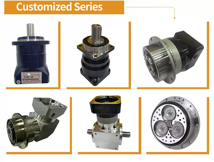
Applications
This report examines the Industrial Planetary Gearbox Market and its current trends. It identifies the pre and post-COVID-19 effects of the industry. It outlines the advantages and disadvantages of the industrial planetary gearbox market. The report also explains the diverse financing resources and business models of the market. It includes the key players in the industry. Hence, it is essential to read this report carefully.
The report includes analysis and forecasts of the global market for planetary gearbox. It includes the product introductions, key business factors, regional and type segments, and end-users. It covers the sales and revenue of the market for each application field. The report also includes the regional and country-level market data. It also focuses on the market share of the key companies operating in the industry. It covers the competitive scenario in the global planetary gearbox market.
Another popular application for planetary gearboxes is in the toy industry. It is possible to design toys that look stunning with planetary gear systems. In addition to toys, clock makers also benefit from the planetary arrangement. In addition to producing a good-looking clock, this gearbox can reduce inertia and improve its efficiency. The planetary gearbox is easy to maintain, which makes it a good choice for clock applications.
In addition to traditional gear reductions, planetary gears are also used for 3D printing. Their huge gear ratio makes 3D printing easier. Furthermore, planetary gears are used to drive stepper motors, which turn much faster and produce a desired output. There are numerous industrial uses for planetary gearboxes. This article has explored a few of the most common ones. And don’t forget to explore their uses.


editor by CX 2023-06-09
China high quality high quality gearbox reductor gear box 90 degree shaft gear reducer qm gearbox k helical bevel gear electric motor speed reducer with Best Sales
Warranty: 3 years
Applicable Industries: Hotels, Garment Shops, Building Material Shops, Manufacturing Plant, Machinery Repair Shops, Food & Beverage Factory, Farms, Restaurant, Home Use, Retail, Food Shop, High Precision Geared Speed Reducer Planetary Gearbox 90 degree low noise right angle gearbox precision Planetary gearbox Printing Shops, Construction works , Energy & Mining, Food & Beverage Shops, Advertising Company
Customized support: OEM, ODM, OBM
Gearing Arrangement: Helical
Output Torque: 470000Nm
Input Speed: 750-1500rpm
Output Speed: 1.7~1200rpm
Certification: ISO9001-2008
Mount Position: Foot Mounted
Bearing: C&U
Packaging Details: Standard wooden case
Helical speed reducer with motor for with cooling system H/b Series Gear Reducer Hseries high power transmission speed reducer
H/B series high power speed gear reducer industrial gearbox for concrete mixer has the features of high versatility,good combination and heavy loading capability, along with other merits such as easy to attain various transmission ratios, high efficiency, low vibration and high permissible axis radial load.
1) Output speed: 1.7~1200r/min
2) Output torque: up to 47, High Precision 200W Square Flange Low Backlash Transmission Speed reducer Planetary Gearbox reducer 000N.m3) Motor power: 2.52~5366kW4) Mounted form: foot-mounted ,flange-mounted, axis mounted, shrink mounted
| Product Name | H/B series high power speed gear reducer industrial gearbox for concrete mixer |
| Housing Material | HT 250 Cast Iron |
| Gear Material | 20CrMnTi |
| Shaft Material | 20CrMnTi |
| Gear Processing | Grinding finish by HOFLER Grinding Machines |
| Color | Customized |
| Noise Test | Bellow 65dB |
| Warranty | 1 year |
Delivery Details : 15-30 working days upon payment
Delivery FAQ Q1: What information should I tell you to confirm the product? A: Model/Size, Transmission Ratio, Shaft directions & Order quantity.
Q2: What can i do if I don’t know which 1 I need?A: Don’t worry, Send as much information as you can, our team will help you find the right 1 you are looking for.
Q3: What is your product warranty period?A:We offer 1 year warranty since the vessel departure date left China.
If you have any question, High precision speed stepper motor planetary gearbox reducer pls feel free to contact us.
Contact us
How to Compare Different Types of Spur Gears
When comparing different types of spur gears, there are several important considerations to take into account. The main considerations include the following: Common applications, Pitch diameter, and Addendum circle. Here we will look at each of these factors in more detail. This article will help you understand what each type of spur gear can do for you. Whether you’re looking to power an electric motor or a construction machine, the right gear for the job will make the job easier and save you money in the long run.
Common applications
Among its many applications, a spur gear is widely used in airplanes, trains, and bicycles. It is also used in ball mills and crushers. Its high speed-low torque capabilities make it ideal for a variety of applications, including industrial machines. The following are some of the common uses for spur gears. Listed below are some of the most common types. While spur gears are generally quiet, they do have their limitations.
A spur gear transmission can be external or auxiliary. These units are supported by front and rear casings. They transmit drive to the accessory units, which in turn move the machine. The drive speed is typically between 5000 and 6000 rpm or 20,000 rpm for centrifugal breathers. For this reason, spur gears are typically used in large machinery. To learn more about spur gears, watch the following video.
The pitch diameter and diametral pitch of spur gears are important parameters. A diametral pitch, or ratio of teeth to pitch diameter, is important in determining the center distance between two spur gears. The center distance between two spur gears is calculated by adding the radius of each pitch circle. The addendum, or tooth profile, is the height by which a tooth projects above the pitch circle. Besides pitch, the center distance between two spur gears is measured in terms of the distance between their centers.
Another important feature of a spur gear is its low speed capability. It can produce great power even at low speeds. However, if noise control is not a priority, a helical gear is preferable. Helical gears, on the other hand, have teeth arranged in the opposite direction of the axis, making them quieter. However, when considering the noise level, a helical gear will work better in low-speed situations.
Construction
The construction of spur gear begins with the cutting of the gear blank. The gear blank is made of a pie-shaped billet and can vary in size, shape, and weight. The cutting process requires the use of dies to create the correct gear geometry. The gear blank is then fed slowly into the screw machine until it has the desired shape and size. A steel gear blank, called a spur gear billet, is used in the manufacturing process.
A spur gear consists of two parts: a centre bore and a pilot hole. The addendum is the circle that runs along the outermost points of a spur gear’s teeth. The root diameter is the diameter at the base of the tooth space. The plane tangent to the pitch surface is called the pressure angle. The total diameter of a spur gear is equal to the addendum plus the dedendum.
The pitch circle is a circle formed by a series of teeth and a diametrical division of each tooth. The pitch circle defines the distance between two meshed gears. The center distance is the distance between the gears. The pitch circle diameter is a crucial factor in determining center distances between two mating spur gears. The center distance is calculated by adding the radius of each gear’s pitch circle. The dedendum is the height of a tooth above the pitch circle.
Other considerations in the design process include the material used for construction, surface treatments, and number of teeth. In some cases, a standard off-the-shelf gear is the most appropriate choice. It will meet your application needs and be a cheaper alternative. The gear will not last for long if it is not lubricated properly. There are a number of different ways to lubricate a spur gear, including hydrodynamic journal bearings and self-contained gears.
Addendum circle
The pitch diameter and addendum circle are two important dimensions of a spur gear. These diameters are the overall diameter of the gear and the pitch circle is the circle centered around the root of the gear’s tooth spaces. The addendum factor is a function of the pitch circle and the addendum value, which is the radial distance between the top of the gear tooth and the pitch circle of the mating gear.
The pitch surface is the right-hand side of the pitch circle, while the root circle defines the space between the two gear tooth sides. The dedendum is the distance between the top of the gear tooth and the pitch circle, and the pitch diameter and addendum circle are the two radial distances between these two circles. The difference between the pitch surface and the addendum circle is known as the clearance.
The number of teeth in the spur gear must not be less than 16 when the pressure angle is twenty degrees. However, a gear with 16 teeth can still be used if its strength and contact ratio are within design limits. In addition, undercutting can be prevented by profile shifting and addendum modification. However, it is also possible to reduce the addendum length through the use of a positive correction. However, it is important to note that undercutting can happen in spur gears with a negative addendum circle.
Another important aspect of a spur gear is its meshing. Because of this, a standard spur gear will have a meshing reference circle called a Pitch Circle. The center distance, on the other hand, is the distance between the center shafts of the two gears. It is important to understand the basic terminology involved with the gear system before beginning a calculation. Despite this, it is essential to remember that it is possible to make a spur gear mesh using the same reference circle.
Pitch diameter
To determine the pitch diameter of a spur gear, the type of drive, the type of driver, and the type of driven machine should be specified. The proposed diametral pitch value is also defined. The smaller the pitch diameter, the less contact stress on the pinion and the longer the service life. Spur gears are made using simpler processes than other types of gears. The pitch diameter of a spur gear is important because it determines its pressure angle, the working depth, and the whole depth.
The ratio of the pitch diameter and the number of teeth is called the DIAMETRAL PITCH. The teeth are measured in the axial plane. The FILLET RADIUS is the curve that forms at the base of the gear tooth. The FULL DEPTH TEETH are the ones with the working depth equal to 2.000 divided by the normal diametral pitch. The hub diameter is the outside diameter of the hub. The hub projection is the distance the hub extends beyond the gear face.
A metric spur gear is typically specified with a Diametral Pitch. This is the number of teeth per inch of the pitch circle diameter. It is generally measured in inverse inches. The normal plane intersects the tooth surface at the point where the pitch is specified. In a helical gear, this line is perpendicular to the pitch cylinder. In addition, the pitch cylinder is normally normal to the helix on the outside.
The pitch diameter of a spur gear is typically specified in millimeters or inches. A keyway is a machined groove on the shaft that fits the key into the shaft’s keyway. In the normal plane, the pitch is specified in inches. Involute pitch, or diametral pitch, is the ratio of teeth per inch of diameter. While this may seem complicated, it’s an important measurement to understand the pitch of a spur gear.
Material
The main advantage of a spur gear is its ability to reduce the bending stress at the tooth no matter the load. A typical spur gear has a face width of 20 mm and will fail when subjected to 3000 N. This is far more than the yield strength of the material. Here is a look at the material properties of a spur gear. Its strength depends on its material properties. To find out what spur gear material best suits your machine, follow the following steps.
The most common material used for spur gears is steel. There are different kinds of steel, including ductile iron and stainless steel. S45C steel is the most common steel and has a 0.45% carbon content. This type of steel is easily obtainable and is used for the production of helical, spur, and worm gears. Its corrosion resistance makes it a popular material for spur gears. Here are some advantages and disadvantages of steel.
A spur gear is made of metal, plastic, or a combination of these materials. The main advantage of metal spur gears is their strength to weight ratio. It is about one third lighter than steel and resists corrosion. While aluminum is more expensive than steel and stainless steel, it is also easier to machine. Its design makes it easy to customize for the application. Its versatility allows it to be used in virtually every application. So, if you have a specific need, you can easily find a spur gear that fits your needs.
The design of a spur gear greatly influences its performance. Therefore, it is vital to choose the right material and measure the exact dimensions. Apart from being important for performance, dimensional measurements are also important for quality and reliability. Hence, it is essential for professionals in the industry to be familiar with the terms used to describe the materials and parts of a gear. In addition to these, it is essential to have a good understanding of the material and the dimensional measurements of a gear to ensure that production and purchase orders are accurate.


China Professional T Spiral Bevel Gear Reducer T2 T4 T6 90 Degree Transmission Gearbox for Agriculture with Great quality
Product Description
Specs:
one. T sequence sprial bevel gear reducer with numerous sorts are standardized
2. all ratio of 1:1,1.5:twelve:12.5:13:14:1and 5:1 are real types,
three. regular efficiency is 98%.
Benefit:
Self-locking ability
Can be driven straight by motor or other electrical power or guide
Can be tailored according user’s demand from customers
Compact configuration, tiny dimension, lightweight
Hassle-free installation, versatile operation
Substantial dependability and stability
Long services lifestyle
More link kind and many others.
Varieties of Miter Gears
The diverse sorts of miter gears contain Hypoid, Crown, and Spiral. To understand more, read through on. In addition, you may understand about their variances and similarities. This post will give an overview of the various sorts of miter gears. You can also select the sort that fits your requirements by using the information underneath. Soon after you have read through it, you will know how to use them in your task. You’ll also learn how to pair them up by hand, which is particularly helpful if you are operating on a mechanical element.
Bevel gears
Bevel and miter gears are the two employed to hook up two shafts that have various axes. In most situations, these gears are utilised at right angles. The pitch cone of a bevel gear has the exact same condition as that of a spur gear, besides the tooth profile is a bit tapered and has variable depth. The pinions of a bevel gear are usually straight, but can be curved or skew-formed. They can also have an offset crown wheel with straight tooth relative to the axis.
In addition to their industrial applications, miter gears are located in agriculture, bottling, printing, and various industrial sectors. They are used in coal mining, oil exploration, and chemical processes. They are an critical component of conveyors, elevators, kilns, and much more. In truth, miter gears are typically utilised in machine resources, like forklifts and jigsaws.
When taking into consideration which gear is right for a particular application, you’ll need to consider about the software and the design ambitions. For example, you’ll want to know the greatest load that the gear can carry. You can use laptop simulation programs to establish the exact torque essential for a particular application. Miter gears are bevel gears that are geared on a one axis, not two.
To estimate the torque needed for a particular application, you are going to need to have to know the MA of every single bevel gear. Fortunately, you can now do so with CZPT. With the support of this software program, you can produce 3D models of spiral bevel gears. As soon as you’ve developed your product, you can then device it. This can make your occupation considerably simpler! And it really is enjoyable!
In conditions of manufacturing, straight bevel gears are the best to create. The earliest technique for this kind of equipment is a planer with an indexing head. Since the development of CNC machining, nevertheless, far more effective manufacturing approaches have been created. These include CZPT, Revacycle, and Coniflex methods. The CZPT employs the Revacycle program. You can also use a CNC mill to manufacture spiral bevel gears.
Hypoid bevel gears
When it comes to creating hypoid bevel gears for miter and other types of gears, there are many important parameters to think about. In buy to generate large-quality gearings, the mounting distance in between the equipment enamel and the pinion should be inside of a predefined tolerance assortment. In other words, the mounting length between the equipment enamel and pinion must be .05 mm or significantly less.
To make this feasible, the hypoid bevel gearset mesh is made to require sliding action. The result is a silent transmission. It also signifies that higher speeds are attainable without increasing sound levels. In comparison, bevel gears have a tendency to be noisy at high speeds. For these reasons, the hypoid gearset is the most effective way to construct miter gears. Nonetheless, it is important to hold in brain that hypoid gears are not for every software.
Hypoid bevel gears are analogous to spiral bevels, but they do not have intersecting axes. Simply because of this, they can create larger pinions with sleek engagement. Crown bevel gears, on the other hand, have a 90-diploma pitch and parallel tooth. Their geometry and pitch is exclusive, and they have distinct geometrical qualities. There are diverse ways to convey pitch. The diametral pitch is the quantity of enamel, while circumferential measurement is known as the circumference.
The encounter-milling approach is one more strategy employed for the manufacture of hypoid and spiral bevel gears. Encounter-milling makes it possible for gears to be ground for high accuracy and area finish. It also allows for the elimination of heat treatment method and facilitates the generation of predesigned simplicity-off topographies. Experience-milling increases mechanical resistance by as a lot as twenty%. It also minimizes sound levels.
The ANSI/AGMA/ISO standards for geometric dimensioning differ from the greatest practices for manufacturing hypoid and bevel gears. The violation of widespread datum surfaces prospects to a variety of geometrical dimensioning issues. Additionally, hypoid gears want to be developed to incorporate the foundation pitches of the mating pinion and the hypoid bevel gear. This is not attainable with out understanding the foundation pitch of the equipment and the mating pinion.
Crown bevel gears
When selecting crown bevels for a miter gear, you will want to take into account a amount of elements. Particularly, you will require to know the ratio of the tooth load to the bevel gear pitch radius. This will help you choose a bevel equipment that possesses the correct amount of excitation and load potential. Crown bevels are also identified as helical gears, which are a mixture of two bevel gear kinds.
These bevel gears differ from spiral bevels because the bevels are not intersected. This offers you the overall flexibility of employing a bigger pinion and smoother engagement. Crown bevel gears are also named for their distinct tooth portions: the toe, or the part of the equipment closest to the bore, and the heel, or the outermost diameter. The tooth peak is more compact at the toe than it is at the heel, but the height of the equipment is the same at both spots.
Crown bevel gears are cylindrical, with enamel that are angled at an angle. They have a 1:1 equipment ratio and are employed for miter gears and spur gears. Crown bevel gears have a tooth profile that is the same as spur gears but is slightly narrower at the idea, offering them outstanding quietness. Crown bevel gears for miter gears can be created with an offset pinion.
There are many other choices accessible when deciding on a Crown bevel equipment for miter gears. The substance utilized for the gears can differ from plastics to pre-hardened alloys. If you are anxious with the material’s strength, you can pick a pre-hardened alloy with a 32-35 Rc hardness. This alloy also has the gain of currently being much more sturdy than plastic. In addition to being much better, crown bevel gears are also less difficult to lubricate.
Crown bevel gears for miter gears are comparable to spiral bevels. Nevertheless, they have a hyperbolic, not conical, pitch surface. The pinion is typically offset earlier mentioned or under the middle of the gear, which enables for a greater diameter. Crown bevel gears for miter gears are normally greater than hypoid gears. The hypoid gear is frequently used in automobile rear axles. They are useful when the angle of rotation is ninety degrees. And they can be utilized for 1:1 ratios.
Spiral miter gears
Spiral bevel gears are produced by machining the experience area of the tooth. The process follows the Hertz concept of elastic make contact with, in which the dislocations are equivalent to small important dimensions of the contact location and the relative radii of curvature. This approach assumes that the surfaces are parallel and that the strains are small. In addition, it can reduce sound. This can make spiral bevel gears an perfect choice for substantial-speed applications.
The precision machining of CZPT spiral miter gears lowers backlash. They attribute adjustable locking nuts that can specifically adjust the spacing among the gear tooth. The result is diminished backlash and maximum push life. In addition, these gears are adaptable sufficient to accommodate style alterations late in the generation procedure, minimizing risk for OEMs and rising effectiveness and productivity. The benefits of spiral miter gears are outlined underneath.
Spiral bevel gears also have many positive aspects. The most clear of these positive aspects is that they have big-diameter shafts. The greater shaft measurement enables for a bigger diameter equipment, but this signifies a greater gear housing. In flip, this decreases ground clearance, inside place, and excess weight. It also tends to make the drive axle gear bigger, which decreases floor clearance and interior area. Spiral bevel gears are much more effective than spiral bevel gears, but it might be tougher to uncover the right measurement for your application.
Another benefit of spiral miter gears is their tiny size. For the exact same sum of power, a spiral miter gear is smaller than a straight cut miter equipment. Moreover, spiral bevel gears are less probably to bend or pit. They also have increased precision qualities. They are ideal for secondary functions. Spiral miter gears are much more resilient than straight cut kinds and can operate at increased speeds.
A key characteristic of spiral miter gears is their capability to resist put on and tear. Because they are constantly being deformed, they are likely to crack in a way that will increase their use and tear. The result is a harder gear with a much more contoured grain flow. But it is attainable to restore the high quality of your equipment via suitable upkeep. If you have a equipment, it would be in your greatest curiosity to exchange worn components if they are not functioning as they need to.