Product Description
Model Selection
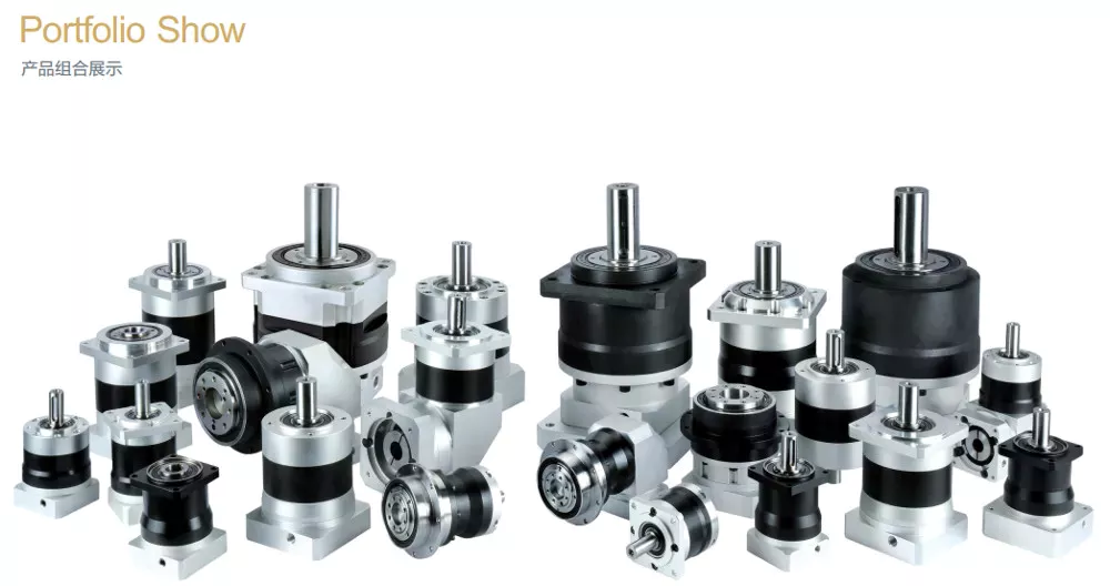
ZD Leader has a wide range of micro motor production lines in the industry, including DC Motor, AC Motor, Brushless Motor, Planetary Gear Motor, Drum Motor, Planetary Gearbox, RV Reducer and Harmonic Gearbox etc. Through technical innovation and customization, we help you create outstanding application systems and provide flexible solutions for various industrial automation situations.
• Model Selection
Our professional sales representive and technical team will choose the right model and transmission solutions for your usage depend on your specific parameters.
• Drawing Request
If you need more product parameters, catalogues, CAD or 3D drawings, please contact us.
• On Your Need
We can modify standard products or customize them to meet your specific needs.
Product Parameters
Type Of RV Reducer
Application Of RV Reeducer
Precision Cycloidal Gearbox is widely used in industrial machinery fields such as machine tool, robot arm, industrial robot, die-casting feeding machine, manipulator for punching machine, AGV driver, bottle-making machine, UV Printer and etc.
Other Products
Company Profile
| Application: | Motor, Machinery |
|---|---|
| Hardness: | Hardened Tooth Surface |
| Installation: | Vertical Type |
| Layout: | Coaxial |
| Gear Shape: | Conical – Cylindrical Gear |
| Step: | Three-Step |
| Customization: |
Available
| Customized Request |
|---|
Planetary Gearbox Advantages and Disadvantages
A planetary gearbox is a type of mechanical drive with a single output shaft. They are suitable for both clockwise and counterclockwise rotations, have less inertia, and operate at higher speeds. Here are some advantages and disadvantages of this type of gearbox. Let us see what these advantages are and why you should use them in your applications. Listed below are some of the benefits of planetary gearboxes.
Suitable for counterclockwise and clockwise rotation
If you want to teach children about the clock hands, you can buy some resources for counterclockwise and asymmetrical rotation. These resources include worksheets for identifying degrees of rotation, writing rules for rotation, and visual processing. You can also use these resources to teach angles. For example, the translation of shapes activity pack helps children learn about the rotation of geometric shapes. Similarly, the visual perception activity sheet helps children understand how to process information visually.
Various studies have been done to understand the anatomical substrate of rotations. In a recent study, CZPT et al. compared the position of the transitional zone electrocardiographically and anatomically. The authors found that the transitional zone was normal in nine of 33 subjects, indicating that rotation is not a sign of disease. Similarly, a counterclockwise rotation may be caused by a genetic or environmental factor.
The core tip data should be designed to work in both clockwise and counterclockwise rotation. Counterclockwise rotation requires a different starting point than a clockwise rotation. In North America, star-delta starting is used. In both cases, the figure is rotated about its point. Counterclockwise rotation, on the other hand, is done in the opposite direction. In addition, it is possible to create counterclockwise rotation using the same gimbal.
Despite its name, both clockwise and counterclockwise rotation requires a certain amount of force to rotate. When rotating clockwise, the object faces upwards. Counterclockwise rotation, on the other hand, starts from the top position and heads to the right. If rotating in the opposite direction, the object turns counterclockwise, and vice versa. The clockwise movement, in contrast, is the reverse of counterclockwise rotation.
Has less inertia
The primary difference between a planetary gearbox and a normal pinion-and-gear reducer is the ratio. A planetary gearbox will produce less inertia, which is an important advantage because it will reduce torque and energy requirements. The ratio of the planetary gearbox to its fixed axis counterpart is a factor of three. A planetary gearbox has smaller gears than a conventional planetary, so its inertia is proportional to the number of planets.
Planetary gears are less inertia than spur gears, and they share the load across multiple gear teeth. This means that they will have low backlash, and this is essential for applications with high start-stop cycles and frequent rotational direction changes. Another benefit is the high stiffness. A planetary gearbox will have less backlash than a spur gearbox, which means that it will be more reliable.
A planetary gearbox can use either spur or helical gears. The former provides higher torque ratings while the latter has less noise and stiffness. Both types of gears are useful in motorsports, aerospace, truck transmissions, and power generation units. They require more assembly time than a conventional parallel shaft gear, but the PD series is the more efficient alternative. PD series planetary gears are suitable for many applications, including servo and robotics.
In contrast, a planetary gear set can have varying input speed. This can affect the frequency response of the gearset. A mathematical model of the two-stage planetary gears has non-stationary effects and correlates with experimental findings. Fig. 6.3 shows an addendum. The dedendum’s minimum value is approximately 1.25m. When the dedendum is at its smallest, the dedendum has less inertia.
Offers greater reliability
The Planetary Gearbox is a better option for driving a vehicle than a standard spur gearbox. A planetary gearbox is less expensive, and they have better backlash, higher load capacity, and greater shock loads. Unlike spur gearboxes, however, mechanical noise is virtually nonexistent. This makes them more reliable in high-shock situations, as well as in a wide range of applications.
The Economy Series has the same power density and torque capacity of the Precision Helical Series, but it lacks the precision of the latter. In contrast, Economy Series planetary gearboxes feature straight spur planetary gearing, and they are used in applications requiring high torque. Both types of gearboxes are compatible with NEMA servo motors. If torque density is important, a planetary gearbox is the best choice.
The Dispersion of External Load: The SSI model has been extensively used to model the reliability of planetary gear systems. This model takes the contact force and fatigue strength of the system as generalized stress and strength. It also provides a theoretical framework to evaluate the reliability of planetary gear systems. It also has many other advantages that make it the preferred choice for high-stress applications. The Planetary Gearbox offers greater reliability and efficiency than traditional rack and pinion gear systems.
Planetary gearing has greater reliability and compact design. Its compact design allows for wider applications with concerns about space and weight. Additionally, the increased torque and reduction makes planetary gearboxes an excellent choice for a wide variety of applications. There are three major types of planetary gearboxes, each with its own advantages. This article describes a few of them. Once you understand their workings, you will be able to choose the best planetary gearbox for your needs.
Has higher operating speeds
When you look at planetary gearboxes, you might be confused about which one to choose. The primary issue is the application of the gearbox. You must also decide on secondary factors like noise level, corrosion resistance, construction, price, and availability worldwide. Some constructors work faster than others and deliver the gearboxes on the same day. However, the latter ones often deliver the planetary gearbox out of stock.
Compared to conventional gearboxes, a planetary gearbox can run at higher speeds when the input speed fluctuates. However, these gears are not very efficient in high-speed applications because of their increased noise levels. This makes planetary gears unsuitable for applications involving a great deal of noise. That is why most planetary gears are used in small-scale applications. There are some exceptions, but in general, a planetary gearbox is better suited for applications with higher operating speeds.
The basic planetary gearbox is a compact alternative to normal pinion-and-gear reducers. They can be used in a wide variety of applications where space and weight are concerns. Its efficiency is also higher, delivering 97% of the power input. It comes in three different types based on the performance. A planetary gearbox can also be classified as a worm gear, a spur gear, or a sprocket.
A planetary gearhead has a high-precision design and can generate substantial torque for their size. It also reduces backlash to two arc-min. Additionally, it is lubricated for life, which means no maintenance is needed. It can fit into a small machine envelope and has a small footprint. Moreover, the helical crowned gearing provides fast positioning. A sealed gearbox prevents abrasive dust from getting into the planetary gearhead.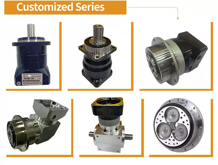
Has drawbacks
The design of a planetary gearbox is compact and enables high torque and load capability in a small space. This gear arrangement also reduces the possibility of wear and tear. Planet gears are arranged in a planetary fashion, allowing gears to shift under load and a uniform distribution of torque. However, some disadvantages of planetary gears must be considered before investing in this gearbox.
While the planetary gearbox is a high precision motion-control device, its design and maintenance requirements are a concern. The bearing load is high, requiring frequent lubrication. Also, they are inaccessible. Despite these drawbacks, planetary gearboxes are suitable for a variety of tasks. They also have low backlash and high torsional stiffness, making them excellent choices for many applications.
As a result, the speed of a planetary gearbox varies with load and speed. At lower ratios, the sun gear becomes too large in relation to the planet gears. As the ratio increases, the sun gear will become too low, reducing torque. The planetary gears also reduce their torque in high-speed environments. Consequently, the ratio is a crucial consideration for planetary gearbox condition monitoring.
Excess drag may result from out-of-tolerance components or excessive lubrication. Drag should be measured both in directions and be within acceptable ranges. Grease and oil lubrication are two common planetary gearbox lubricants, but the choice is largely dependent on your application. While grease lubricates planetary gears well, oil needs maintenance and re-lubrication every few thousand hours.


editor by CX 2023-04-28
China high quality Spur Gear Cutting Rod Stock Helical Spur Gears with Good quality
Merchandise Description
Item Description
Main Positive aspects
1) Powder metallurgy can ensure the accuracy and uniformity of the substance composition ratio.
2) Ideal for making merchandise of the identical shape and massive portions, low manufacturing value.
three) The creation procedure is not afraid of oxidation, and no substance pollution will arise.
four) No subsequent machining processing is essential, preserving supplies and reducing fees.
5) Most difficult metals and compounds, pseudo alloys, porous components can only be made by powder metallurgy
FAQ
Q: Are you trading company or producer ?
A: We are manufacturing unit and trading business
Q: How extended is your shipping time?
A: Typically it is 5-10 times if the goods are in inventory. or it is fifteen-20 days if the products are not in stock, it is in accordance to amount.
Q: Do you give samples ? is it cost-free or extra ?
A: Of course, we could offer the sample for totally free charge but do not spend the cost of freight.
Q: What is your phrases of payment ?
A: Payment=1000USD, thirty% T/T in CZPT ,harmony prior to shippment.
If you have yet another query, pls truly feel free to get in touch with us as below:
Spiral Gears for Appropriate-Angle Correct-Hand Drives
Spiral gears are employed in mechanical methods to transmit torque. The bevel equipment is a certain sort of spiral equipment. It is produced up of two gears that mesh with one an additional. Both gears are connected by a bearing. The two gears should be in mesh alignment so that the damaging thrust will press them jointly. If axial play takes place in the bearing, the mesh will have no backlash. Additionally, the layout of the spiral gear is based on geometrical tooth varieties.
Equations for spiral equipment
The idea of divergence calls for that the pitch cone radii of the pinion and gear be skewed in different directions. This is completed by rising the slope of the convex floor of the gear’s tooth and decreasing the slope of the concave area of the pinion’s tooth. The pinion is a ring-shaped wheel with a central bore and a plurality of transverse axes that are offset from the axis of the spiral teeth.
Spiral bevel gears have a helical tooth flank. The spiral is steady with the cutter curve. The spiral angle b is equivalent to the pitch cone’s genatrix aspect. The mean spiral angle bm is the angle between the genatrix factor and the tooth flank. The equations in Desk 2 are certain for the Unfold Blade and One Side gears from Gleason.
The tooth flank equation of a logarithmic spiral bevel equipment is derived using the formation mechanism of the tooth flanks. The tangential make contact with pressure and the normal strain angle of the logarithmic spiral bevel equipment had been identified to be about 20 levels and 35 levels respectively. These two varieties of motion equations have been used to solve the troubles that arise in determining the transmission stationary. While the idea of logarithmic spiral bevel gear meshing is nonetheless in its infancy, it does offer a great commencing position for understanding how it works.
This geometry has many diverse remedies. Nonetheless, the primary two are defined by the root angle of the equipment and pinion and the diameter of the spiral gear. The latter is a difficult 1 to constrain. A 3D sketch of a bevel equipment tooth is used as a reference. The radii of the tooth place profile are defined by stop stage constraints placed on the bottom corners of the tooth space. Then, the radii of the gear tooth are identified by the angle.
The cone distance Am of a spiral gear is also recognized as the tooth geometry. The cone length need to correlate with the different sections of the cutter path. The cone distance range Am need to be capable to correlate with the strain angle of the flanks. The foundation radii of a bevel gear require not be outlined, but this geometry should be regarded as if the bevel gear does not have a hypoid offset. When establishing the tooth geometry of a spiral bevel gear, the first action is to convert the terminology to pinion rather of equipment.
The typical system is a lot more handy for production helical gears. In addition, the helical gears must be the very same helix angle. The reverse hand helical gears have to mesh with every single other. Also, the profile-shifted screw gears need to have much more complicated meshing. This gear pair can be produced in a related way to a spur equipment. Further, the calculations for the meshing of helical gears are introduced in Desk 7-1.
Style of spiral bevel gears
A proposed layout of spiral bevel gears makes use of a purpose-to-sort mapping approach to decide the tooth surface area geometry. This reliable design is then analyzed with a floor deviation method to determine regardless of whether it is exact. Compared to other right-angle gear sorts, spiral bevel gears are more productive and compact. CZPT Equipment Firm gears comply with AGMA standards. A larger good quality spiral bevel gear set achieves 99% performance.
A geometric meshing pair based mostly on geometric components is proposed and analyzed for spiral bevel gears. This strategy can supply high get in touch with energy and is insensitive to shaft angle misalignment. Geometric factors of spiral bevel gears are modeled and discussed. Speak to styles are investigated, as effectively as the impact of misalignment on the load capacity. In addition, a prototype of the design and style is fabricated and rolling exams are performed to confirm its accuracy.
The three fundamental factors of a spiral bevel equipment are the pinion-equipment pair, the input and output shafts, and the auxiliary flank. The enter and output shafts are in torsion, the pinion-equipment pair is in torsional rigidity, and the technique elasticity is little. These aspects make spiral bevel gears excellent for meshing affect. To boost meshing influence, a mathematical model is designed utilizing the tool parameters and preliminary equipment settings.
In recent several years, a number of developments in producing technologies have been produced to create large-efficiency spiral bevel gears. Scientists these kinds of as Ding et al. optimized the machine settings and cutter blade profiles to eradicate tooth edge make contact with, and the result was an accurate and huge spiral bevel equipment. In truth, this method is even now used right now for the manufacturing of spiral bevel gears. If you are fascinated in this technological innovation, you must read through on!
The design and style of spiral bevel gears is intricate and intricate, requiring the skills of skilled machinists. Spiral bevel gears are the condition of the art for transferring power from 1 system to yet another. Though spiral bevel gears ended up once challenging to manufacture, they are now frequent and extensively utilised in several purposes. In reality, spiral bevel gears are the gold common for appropriate-angle energy transfer.Whilst typical bevel gear equipment can be utilised to manufacture spiral bevel gears, it is quite sophisticated to produce double bevel gears. The double spiral bevel gearset is not machinable with classic bevel gear equipment. Consequently, novel producing approaches have been developed. An additive production strategy was utilized to create a prototype for a double spiral bevel gearset, and the manufacture of a multi-axis CNC machine middle will stick to.
Spiral bevel gears are vital components of helicopters and aerospace power plants. Their durability, stamina, and meshing performance are essential for protection. Several scientists have turned to spiral bevel gears to address these troubles. One challenge is to decrease sounds, enhance the transmission efficiency, and improve their endurance. For this explanation, spiral bevel gears can be more compact in diameter than straight bevel gears. If you are interested in spiral bevel gears, check out this post.
Restrictions to geometrically acquired tooth forms
The geometrically attained tooth kinds of a spiral equipment can be calculated from a nonlinear programming issue. The tooth strategy Z is the linear displacement mistake together the get in touch with standard. It can be calculated employing the formula provided in Eq. (23) with a couple of added parameters. Nevertheless, the result is not accurate for little loads due to the fact the signal-to-sounds ratio of the pressure sign is small.
Geometrically attained tooth varieties can direct to line and position speak to tooth types. Nevertheless, they have their restrictions when the tooth bodies invade the geometrically acquired tooth type. This is known as interference of tooth profiles. Whilst this restrict can be get over by several other strategies, the geometrically received tooth kinds are constrained by the mesh and strength of the tooth. They can only be used when the meshing of the gear is satisfactory and the relative movement is enough.
During the tooth profile measurement, the relative situation in between the gear and the LTS will continuously modify. The sensor mounting area should be parallel to the rotational axis. The genuine orientation of the sensor could differ from this perfect. This might be owing to geometrical tolerances of the gear shaft assistance and the system. However, this influence is minimum and is not a severe difficulty. So, it is achievable to acquire the geometrically received tooth forms of spiral equipment without having going through expensive experimental techniques.
The measurement method of geometrically obtained tooth types of a spiral gear is primarily based on an best involute profile created from the optical measurements of one end of the equipment. This profile is assumed to be nearly excellent primarily based on the common orientation of the LTS and the rotation axis. There are small deviations in the pitch and yaw angles. Lower and upper bounds are determined as – 10 and -ten degrees respectively.
The tooth kinds of a spiral equipment are derived from substitution spur toothing. Nevertheless, the tooth form of a spiral equipment is nevertheless subject to different constraints. In addition to the tooth condition, the pitch diameter also affects the angular backlash. The values of these two parameters fluctuate for every single gear in a mesh. They are related by the transmission ratio. After this is recognized, it is achievable to produce a equipment with a corresponding tooth form.
As the size and transverse base pitch of a spiral gear are the identical, the helix angle of each and every profile is equal. This is essential for engagement. An imperfect base pitch benefits in an uneven load sharing among the gear teeth, which sales opportunities to greater than nominal loads in some teeth. This qualified prospects to amplitude modulated vibrations and sound. In addition, the boundary stage of the root fillet and involute could be decreased or eradicate contact prior to the suggestion diameter.


China Professional Customized Large CNC Machining Stainless Steel Spur Helical Gear Wheel with Free Design Custom
Solution Description
one.How can I get the quotation?
Remember to give us your drawing,quantity,excess weight and material of the item.
2.If you don’t have the drawing,can you make drawing for me? Indeed,we are CZPT to make the drawing of your sample copy
the sample.
3.When can I get the sample and your main order time? Sample time: 35-40 days following start off to make mildew. Get time: 35-forty days,
the exact time relies upon on product.
4.What is your payment approach? Tooling:100% T/T innovative Order time:fifty% deposit,50%to be compensated prior to cargo.
5.Which sort of file format you can read through? PDF, IGS, DWG, Phase, MAX
6.What is your surface area treatment? Like: powder coating, sand blasting, painting, polishing, acid pickling, anodizing, enamel, zinc plating, scorching-dip galvanizing, chrome plating.
7.What is your way of packing? Typically we pack items in accordance to customers’ needs.
Synthesis of Epicyclic Gear Trains for Automotive Automatic Transmissions
In this article, we will talk about the synthesis of epicyclic gear trains for automotive automatic transmissions, their purposes, and cost. After you have completed reading through, you may want to do some investigation on the engineering yourself. Below are some hyperlinks to even more reading through on this subject. They also include an application in hybrid car transmissions. Let’s seem at the basic concepts of epicyclic gear trains. They are very productive and are a promising substitute to traditional gearing techniques.
Synthesis of epicyclic equipment trains for automotive computerized transmissions
The principal purpose of automotive automated transmissions is to keep motor-generate wheel stability. The kinematic construction of epicyclic gear trains (EGTs) is derived from graph representations of these gear trains. The synthesis method is based mostly on an algorithm that generates admissible epicyclic equipment trains with up to 10 back links. This algorithm allows designers to design automobile gear trains that have greater performance and far better motor-push wheel equilibrium.
In this paper, we current a MATLAB optimization approach for identifying the gear ratios of epicyclic transmission mechanisms. We also enumerate the variety of tooth for all gears. Then, we estimate the total velocity ratios of the attained EGTs. Then, we evaluate the feasibility of the proposed epicyclic equipment trains for automotive computerized transmissions by comparing their structural traits.
A six-website link epicyclic gear train is depicted in the adhering to functional diagram. Every url is represented by a double-bicolor graph. The numbers on the graph depict the corresponding links. Every url has numerous joints. This can make it feasible for a person to create different configurations for each EGT. The figures on the various graphs have different meanings, and the identical applies to the double-bicolor figure.
In the up coming chapter of this report, we discuss the synthesis of epicyclic equipment trains for automotive computerized transaxles. SAE Global is an global business of engineers and technical experts with core competencies in aerospace and automotive. Its charitable arm, the SAE Basis, supports a lot of plans and initiatives. These incorporate the Collegiate Style Sequence and A Globe In Motion(r) and the SAE Foundation’s A Globe in Motion(r) award.
Purposes
The epicyclic gear system is a type of planetary equipment practice. It can achieve a excellent velocity reduction in a modest room. In autos, epicyclic gear trains are often employed for the computerized transmission. These gear trains are also helpful in hoists and pulley blocks. They have a lot of purposes in each mechanical and electrical engineering. They can be utilized for substantial-velocity transmission and require considerably less place than other sorts of gear trains.
The advantages of an epicyclic gear practice contain its compact structure, low bodyweight, and high power density. However, they are not with no down sides. Gear losses in epicyclic equipment trains are a consequence of friction in between equipment tooth surfaces, churning of lubricating oil, and the friction in between shaft support bearings and sprockets. This reduction of electrical power is called latent electrical power, and previous research has shown that this decline is remarkable.
The epicyclic equipment teach is frequently employed for high-pace transmissions, but it also has a little footprint and is appropriate for a variety of programs. It is utilised as differential gears in pace frames, to generate bobbins, and for the Roper good allow-off in looms. In addition, it is easy to fabricate, generating it an superb choice for a selection of industrial options.
An additional example of an epicyclic gear prepare is the planetary equipment train. It is made up of two gears with a ring in the middle and the solar gear in the outer ring. Every gear is mounted so that its middle rotates about the ring of the other equipment. The planet gear and solar gear are designed so that their pitch circles do not slip and are in sync. The world equipment has a position on the pitch circle that traces the epicycloid curve.
This equipment system also provides a reduced MTTR than other types of planetary gears. The principal downside of these equipment sets is the huge variety of bearings they require to operate. Moreover, planetary gears are a lot more servicing-intense than parallel shaft gears. This makes them far more challenging to keep an eye on and restore. The MTTR is also reduced in contrast to parallel shaft gears. They can also be a little off on their axis, leading to them to misalign or lose their performance.
Yet another illustration of an epicyclic equipment train is the differential equipment box of an vehicle. These gears are employed in wrist watches, lathe machines, and automotives to transmit power. In addition, they are used in a lot of other programs, like in aircrafts. They are silent and resilient, generating them an excellent selection for many programs. They are employed in transmission, textile devices, and even aerospace. A pitch position is the path amongst two teeth in a gear set. The axial pitch of one particular gear can be improved by growing its base circle.
An epicyclic gear is also recognized as an involute gear. The number of tooth in each and every equipment establishes its price of rotation. A 24-tooth sunlight gear creates an N-tooth planet gear with a ratio of 3/2. A 24-tooth sun gear equals a -3/2 world equipment ratio. Consequently, the epicyclic equipment system supplies large torque for driving wheels. However, this equipment practice is not extensively used in vehicles.
Cost
The expense of epicyclic gearing is reduce when they are tooled instead than created on a normal N/C milling equipment. The epicyclic carriers should be created in a casting and tooled making use of a solitary-function equipment that has a number of cutters to cut the materials at the same time. This method is broadly utilised for industrial purposes and is notably useful in the automotive sector. The benefits of a nicely-created epicyclic equipment transmission are numerous.
An case in point of this is the planetary arrangement exactly where the planets orbit the sunlight although rotating on its shaft. The ensuing pace of each gear depends on the amount of teeth and the pace of the provider. Epicyclic gears can be tough to calculate relative speeds, as they should figure out the relative speed of the sunshine and the earth. The fixed sunshine is not at zero RPM at mesh, so the relative pace must be calculated.
In purchase to establish the mesh energy transmission, epicyclic gears have to be designed to be ready to “float.” If the tangential load is as well reduced, there will be less load sharing. An epicyclic gear need to be capable to enable “float.” It ought to also allow for some tangential load and pitch-line velocities. The increased these aspects, the a lot more effective the gear set will be.
An epicyclic gear practice is composed of two or more spur gears put circumferentially. These gears are organized so that the earth equipment rolls within the pitch circle of the mounted outer gear ring. This curve is called a hypocycloid. An epicyclic gear train with a earth participating a solar equipment is referred to as a planetary gear practice. The sunshine equipment is mounted, while the earth gear is pushed.
An epicyclic gear train contains a number of meshes. Every equipment has a distinct number of meshes, which interprets into RPM. The epicyclic equipment can improve the load application frequency by translating input torque into the meshes. The epicyclic gear practice is made up of 3 gears, the sun, world, and ring. The sun equipment is the middle equipment, whilst the planets orbit the solar. The ring equipment has many tooth, which boosts the gear pace.
Another sort of epicyclic equipment is the planetary gearbox. This gear box has a number of toothed wheels rotating about a central shaft. Its minimal-profile design can make it a popular selection for place-constrained apps. This gearbox variety is used in automatic transmissions. In addition, it is utilised for many industrial employs involving electric powered gear motors. The type of gearbox you use will rely on the speed and torque of the enter and output shafts.
China wholesaler Forging Hobbing Die Casting Gear Steel Metal Differential Drive Motor Slew CZPT Rack Pinion Wheel Worm Shaft Spiral Helical Spur Bevel Transmission Gears with Great quality
Merchandise Description
Forging Hobbing Die Casting Gear Metal Steel Differential Generate Motor Slew CZPT Rack Pinion Wheel Worm Shaft Spiral Helical Spur Bevel Transmission Gears
Solution Description
Specifction:
Generation process:
Molding Chopping, Equipment Hobbing, Equipment Milling, Equipment Shaping, Equipment Broaching,Gear Shaving, Equipment Grinding and Equipment Lapping.
Related Merchandise:
Business Profile
HangZhou CZPT CZPT Co.,LTD proven in 2009, is a expert manufacture engaged in growth, production, revenue and service of timing pulley, precise spur gears, helical gears, bevel equipment, worm& worm equipment and so on. We positioned in HangZhou with handy transposition excite. CZPT CZPT dedicated to rigid high quality management and considerate customer support. Our knowledgeable staffs are usually obtainable to go over your demands, and satisfy your fulfillment.
Inspection:
Hefa Gear CZPT committed to rigid quality manage.” Focus and Professional on the Growth of Conveyor Area” this is CZPT CZPT concentrate on. Operate step by step, CZPT often offer achievement answer in exact conveyor discipline. Offering ideal price, super services and normal shipping and delivery are always our priorities.
Packaging & Delivery
FAQ
If you are interested in our items, make sure you notify us which components, kind, width, duration u want.
How to Design and style a Forging Spur Gear
Prior to you start planning your very own spur gear, you require to recognize its principal factors. Among them are Forging, Keyway, Spline, Established screw and other sorts. Understanding the variations among these kinds of spur gears is essential for producing an educated selection. To discover far more, preserve looking through. Also, do not be reluctant to speak to me for guidance! Listed underneath are some helpful guidelines and tips to style a spur gear. Hopefully, they will support you design the spur gear of your desires.
Forging spur gears
Forging spur gears is one of the most crucial processes of automotive transmission parts. The producing method is complex and involves many actions, such as blank spheroidizing, hot forging, annealing, phosphating, and saponification. The substance used for spur gears is normally 20CrMnTi. The approach is concluded by implementing a constant by means of extrusion forming method with dies made for the sizing band duration L and Splitting angle thickness T.
The approach of forging spur gears can also use polyacetal (POM), a powerful plastic commonly employed for the manufacture of gears. This materials is straightforward to mildew and form, and after hardening, it is really rigid and abrasion resistant. A number of metals and alloys are employed for spur gears, like cast metal, stainless metal, and aluminum. Detailed underneath are the various kinds of resources used in equipment manufacturing and their positive aspects and disadvantages.
A spur gear’s tooth measurement is measured in modules, or m. Each and every number represents the number of tooth in the gear. As the variety of teeth increases, so does its size. In standard, the greater the amount of tooth, the more substantial the module is. A higher module equipment has a large force angle. It’s also essential to remember that spur gears have to have the very same module as the gears they are utilized to travel.
Set screw spur gears
A modern day sector can not perform with no set screw spur gears. These gears are highly effective and are broadly used in a assortment of applications. Their design and style involves the calculation of speed and torque, which are each vital elements. The MEP product, for occasion, considers the shifting rigidity of a tooth pair together its path. The benefits are employed to determine the sort of spur gear necessary. Shown beneath are some suggestions for selecting a spur equipment:
Sort A. This type of gear does not have a hub. The equipment alone is flat with a modest hole in the center. Set screw gears are most commonly utilised for lightweight applications with no loads. The metal thickness can range from .25 mm to 3 mm. Set screw gears are also employed for big equipment that need to be powerful and durable. This report gives an introduction to the various kinds of spur gears and how they vary from 1 an additional.
Pin Hub. Pin hub spur gears use a set screw to secure the pin. These gears are usually related to a shaft by dowel, spring, or roll pins. The pin is drilled to the precise diameter to match within the gear, so that it does not arrive free. Pin hub spur gears have large tolerances, as the gap is not big sufficient to totally grip the shaft. This type of equipment is usually the most high-priced of the 3.
Keyway spur gears
In today’s modern day industry, spur equipment transmissions are extensively used to transfer electrical power. These varieties of transmissions give superb performance but can be susceptible to electricity losses. These losses must be approximated for the duration of the design and style procedure. A key element of this analysis is the calculation of the get in touch with region (2b) of the equipment pair. However, this worth is not necessarily relevant to each and every spur equipment. Right here are some illustrations of how to calculate this region. (See Determine 2)
Spur gears are characterised by getting tooth parallel to the shafts and axis, and a pitch line velocity of up to 25 m/s is considered high. In addition, they are far more efficient than helical gears of the very same size. Unlike helical gears, spur gears are typically deemed good gears. They are often used for applications in which sounds manage is not an situation. The symmetry of the spur gear helps make them especially suited for purposes in which a continuous pace is necessary.
Aside from using a helical spur gear for the transmission, the gear can also have a regular tooth condition. As opposed to helical gears, spur gears with an involute tooth form have thick roots, which helps prevent wear from the teeth. These gears are very easily created with typical production equipment. The involute form is an ideal choice for little-scale generation and is one of the most well-known varieties of spur gears.
Spline spur gears
When considering the types of spur gears that are utilised, it’s important to notice the differences in between the two. A spur equipment, also referred to as an involute gear, generates torque and regulates speed. It’s most typical in automobile engines, but is also utilized in each day appliances. Nonetheless, 1 of the most substantial downsides of spur gears is their noise. Since spur gears mesh only one particular tooth at a time, they generate a substantial sum of anxiety and sound, producing them unsuitable for each day use.
The speak to pressure distribution chart signifies the flank location of every single equipment tooth and the length in both the axial and profile path. A high contact spot is located toward the heart of the gear, which is brought on by the micro-geometry of the gear. A constructive l benefit implies that there is no misalignment of the spline tooth on the interface with the helix hand. The opposite is real for unfavorable l values.
Using an upper certain technique, Abdul and Dean analyzed the forging of spur gear forms. They assumed that the tooth profile would be a straight line. They also examined the non-dimensional forging stress of a spline. Spline spur gears are commonly employed in motors, gearboxes, and drills. The strength of spur gears and splines is largely dependent on their radii and tooth diameter.
SUS303 and SUS304 stainless metal spur gears
Stainless metal spur gears are produced utilizing different tactics, which rely on the substance and the software. The most frequent process employed in production them is reducing. Other processes include rolling, casting, and forging. In addition, plastic spur gears are developed by injection molding, depending on the amount of production required. SUS303 and SUS304 stainless steel spur gears can be made utilizing a assortment of resources, such as structural carbon steel S45C, grey cast iron FC200, nonferrous metal C3604, engineering plastic MC901, and stainless steel.
The variances among 304 and 303 stainless steel spur gears lie in their composition. The two kinds of stainless metal share a widespread style, but have varying chemical compositions. China and Japan use the letters SUS304 and SUS303, which refer to their different levels of composition. As with most kinds of stainless metal, the two various grades are produced to be used in industrial purposes, such as planetary gears and spur gears.
Stainless metal spur gears
There are a number of issues to look for in a stainless steel spur gear, which includes the diametral pitch, the quantity of enamel for each device diameter, and the angular velocity of the teeth. All of these factors are vital to the functionality of a spur gear, and the proper dimensional measurements are important to the design and style and functionality of a spur gear. Individuals in the sector ought to be common with the conditions employed to describe spur equipment elements, equally to make certain clarity in creation and in obtain orders.
A spur equipment is a type of precision cylindrical gear with parallel teeth arranged in a rim. It is utilized in different apps, these kinds of as outboard motors, winches, development gear, garden and yard equipment, turbine drives, pumps, centrifuges, and a range of other equipment. A spur gear is typically created from stainless steel and has a large level of durability. It is the most frequently employed variety of equipment.
Stainless metal spur gears can arrive in numerous diverse designs and sizes. Stainless steel spur gears are usually created of SUS304 or SUS303 stainless steel, which are utilized for their increased machinability. These gears are then warmth-handled with nitriding or tooth area induction. In contrast to typical gears, which need to have tooth grinding right after heat-treating, stainless steel spur gears have a lower dress in rate and higher machinability.
China supplier Forging Hobbing Die Casting Gear Steel Metal Differential Drive Motor Slew CZPT Rack Pinion Wheel Worm Shaft Spiral Helical Spur Bevel Transmission Gears near me manufacturer
Merchandise Description
Forging Hobbing Die Casting Equipment Steel Steel Differential Generate Motor Slew CZPT Rack Pinion Wheel Worm Shaft Spiral Helical Spur Bevel Transmission Gears
Click below for much more particulars!
Customization method
Assist Custom-made Gears from Customers’ drawings and samples and A variety of non-standard customization
one.Merchandise Discussions
Clients ship drawings oramples, and quotation according to customers’ requirements.
two.Molds developing
Developing 3D drawings and optimizing the merchandise.
three.Drawing affirmation
Sending the mould drawing tothe customers , and the customers sign for confirmation.
4.Molds Development
Manufacture molds accurately and correctly according to the drawings.
five.Moulds Inspection and Moulds Check
Detect a variety of indicators of molds and optimization of inner cavities.
six.Sample Aprroval from Buyer
Clients approve the samples and confirm them for bulk production.
7.Mass Creation
Bulk generation according to customers’s PO
eight.PO Finished
Delivery to the buyer andthe consumers receive the gears.
If you need to have other personalized requirements, make sure you click on below to get in touch with us!
Why Select Us
We enthusiastically offer sincere and prompt provider to our consumers and build sustainable business romantic relationship with them.
a hundred% Manufacturing unit inspection, we are responsible for any problems subjected to malfunction in warranty period.
We Can Provide You:
- On-time Shipping and delivery with Much more Selection
- Product Answers and Services
- Lengthy Good quality Assure
- Nearby Technological Assistance
- Fast Reaction to Customers’ Feedbacks in 24 several hours
Also I would like to get this opportunity to give a quick introduction of our At any time-Energy organization:
Our company is a CZPT producer of agriculture gearbox,worm minimize gearbox, PTO shafts, Sprockets ,rollar chains, bevel gear, pulleys and racks in china.
We have exported a lot of products to our consumers all in excess of the entire world, we have long-time expertise and robust engineering help.
You also can check our website to know for much more particulars, if you need our products catalogue, you should make contact with with us.
Firm info
Types of Miter Gears
The various varieties of miter gears contain Hypoid, Crown, and Spiral. To discover much more, read through on. In addition, you are going to find out about their variations and similarities. This article will offer an overview of the distinct varieties of miter gears. You can also decide on the type that suits your requirements by making use of the information below. Following you’ve got read through it, you’ll know how to use them in your project. You are going to also learn how to pair them up by hand, which is especially beneficial if you are working on a mechanical element.
Bevel gears
Bevel and miter gears are both employed to join two shafts that have distinct axes. In most cases, these gears are utilised at correct angles. The pitch cone of a bevel equipment has the very same shape as that of a spur equipment, apart from the tooth profile is marginally tapered and has variable depth. The pinions of a bevel gear are generally straight, but can be curved or skew-formed. They can also have an offset crown wheel with straight enamel relative to the axis.
In addition to their industrial apps, miter gears are found in agriculture, bottling, printing, and numerous industrial sectors. They are employed in coal mining, oil exploration, and chemical procedures. They are an crucial component of conveyors, elevators, kilns, and much more. In simple fact, miter gears are typically utilized in device equipment, like forklifts and jigsaws.
When contemplating which gear is correct for a specific application, you’ll need to believe about the software and the design objectives. For instance, you may want to know the highest load that the equipment can have. You can use personal computer simulation applications to decide the exact torque needed for a certain software. Miter gears are bevel gears that are geared on a single axis, not two.
To calculate the torque required for a distinct software, you are going to need to have to know the MA of every bevel gear. Fortunately, you can now do so with CZPT. With the support of this software program, you can make 3D types of spiral bevel gears. Once you’ve got created your model, you can then machine it. This can make your occupation a lot simpler! And it’s enjoyable!
In conditions of production, straight bevel gears are the easiest to produce. The earliest strategy for this variety of gear is a planer with an indexing head. Since the development of CNC machining, however, more efficient producing strategies have been produced. These contain CZPT, Revacycle, and Coniflex methods. The CZPT uses the Revacycle method. You can also use a CNC mill to manufacture spiral bevel gears.
Hypoid bevel gears
When it will come to developing hypoid bevel gears for miter and other types of gears, there are several crucial parameters to take into account. In buy to produce higher-top quality gearings, the mounting length between the gear teeth and the pinion should be in a predefined tolerance selection. In other words, the mounting length amongst the gear enamel and pinion need to be .05 mm or considerably less.
To make this possible, the hypoid bevel gearset mesh is developed to include sliding action. The outcome is a quiet transmission. It also means that larger speeds are attainable without escalating sounds ranges. In comparison, bevel gears tend to be noisy at substantial speeds. For these motives, the hypoid gearset is the most productive way to create miter gears. Even so, it really is critical to keep in thoughts that hypoid gears are not for each application.
Hypoid bevel gears are analogous to spiral bevels, but they never have intersecting axes. Since of this, they can make greater pinions with sleek engagement. Crown bevel gears, on the other hand, have a 90-degree pitch and parallel tooth. Their geometry and pitch is special, and they have specific geometrical qualities. There are diverse ways to convey pitch. The diametral pitch is the number of enamel, even though circumferential measurement is known as the circumference.
The face-milling strategy is yet another method utilized for the manufacture of hypoid and spiral bevel gears. Confront-milling allows gears to be floor for high accuracy and area finish. It also makes it possible for for the elimination of warmth treatment and facilitates the creation of predesigned simplicity-off topographies. Experience-milling boosts mechanical resistance by as much as 20%. It also reduces sound amounts.
The ANSI/AGMA/ISO standards for geometric dimensioning differ from the very best techniques for production hypoid and bevel gears. The violation of frequent datum surfaces sales opportunities to a variety of geometrical dimensioning issues. In addition, hypoid gears want to be designed to incorporate the base pitches of the mating pinion and the hypoid bevel gear. This is not possible with no understanding the base pitch of the gear and the mating pinion.
Crown bevel gears
When choosing crown bevels for a miter equipment, you will need to contemplate a number of elements. Specifically, you will need to have to know the ratio of the tooth load to the bevel equipment pitch radius. This will aid you pick a bevel gear that possesses the right sum of excitation and load ability. Crown bevels are also recognized as helical gears, which are a mixture of two bevel gear varieties.
These bevel gears differ from spiral bevels simply because the bevels are not intersected. This provides you the flexibility of employing a greater pinion and smoother engagement. Crown bevel gears are also named for their various tooth parts: the toe, or the portion of the gear closest to the bore, and the heel, or the outermost diameter. The tooth height is smaller at the toe than it is at the heel, but the peak of the gear is the exact same at equally areas.
Crown bevel gears are cylindrical, with tooth that are angled at an angle. They have a 1:1 gear ratio and are utilized for miter gears and spur gears. Crown bevel gears have a tooth profile that is the very same as spur gears but is marginally narrower at the suggestion, giving them outstanding quietness. Crown bevel gears for miter gears can be manufactured with an offset pinion.
There are numerous other options available when deciding on a Crown bevel gear for miter gears. The content employed for the gears can differ from plastics to pre-hardened alloys. If you are involved with the material’s power, you can decide on a pre-hardened alloy with a 32-35 Rc hardness. This alloy also has the benefit of being far more tough than plastic. In addition to being much better, crown bevel gears are also simpler to lubricate.
Crown bevel gears for miter gears are related to spiral bevels. However, they have a hyperbolic, not conical, pitch surface. The pinion is usually offset above or under the center of the gear, which makes it possible for for a greater diameter. Crown bevel gears for miter gears are usually bigger than hypoid gears. The hypoid gear is generally employed in automobile rear axles. They are helpful when the angle of rotation is 90 levels. And they can be utilized for 1:1 ratios.
Spiral miter gears
Spiral bevel gears are produced by machining the confront area of the teeth. The process follows the Hertz theory of elastic contact, where the dislocations are equivalent to modest significant dimensions of the get in touch with spot and the relative radii of curvature. This strategy assumes that the surfaces are parallel and that the strains are small. Moreover, it can reduce noise. This helps make spiral bevel gears an best decision for substantial-speed programs.
The precision machining of CZPT spiral miter gears minimizes backlash. They characteristic adjustable locking nuts that can specifically modify the spacing amongst the gear enamel. The outcome is diminished backlash and maximum generate lifestyle. In addition, these gears are versatile ample to accommodate design and style modifications late in the creation approach, reducing threat for OEMs and growing efficiency and efficiency. The benefits of spiral miter gears are outlined under.
Spiral bevel gears also have a lot of rewards. The most apparent of these rewards is that they have large-diameter shafts. The more substantial shaft dimension makes it possible for for a bigger diameter gear, but this means a bigger equipment housing. In turn, this decreases floor clearance, interior area, and bodyweight. It also makes the push axle gear greater, which minimizes floor clearance and interior place. Spiral bevel gears are much more effective than spiral bevel gears, but it might be more difficult to find the correct size for your software.
An additional reward of spiral miter gears is their small dimensions. For the very same amount of energy, a spiral miter gear is scaled-down than a straight minimize miter gear. Moreover, spiral bevel gears are less probably to bend or pit. They also have higher precision properties. They are appropriate for secondary operations. Spiral miter gears are a lot more tough than straight minimize kinds and can operate at larger speeds.
A crucial characteristic of spiral miter gears is their capability to resist put on and tear. Simply because they are continually becoming deformed, they tend to crack in a way that boosts their dress in and tear. The result is a harder gear with a a lot more contoured grain movement. But it is feasible to restore the high quality of your equipment by means of proper maintenance. If you have a equipment, it would be in your greatest desire to substitute worn elements if they aren’t performing as they need to.